SIPLACE D3 规格说明书英文版.pdf - 第11页
11 Placement Heads Standard Functions / Options 12-nozzle Collect & Place head 6-nozzle Collect & Place head S tandard- functions Camera, vacuum sensor , force measurement, PCB warpage, check, individual recordin…
10
Placement Heads
Overview
Head Modularity
The SIPLACE D3 is charac-
terized by maximum flexibil-
ity in the production process.
This flexibility is partly due to
the head modularity of the
placement machine as it
allows different placement
head variants to be config-
ured to suit the production
requirements.
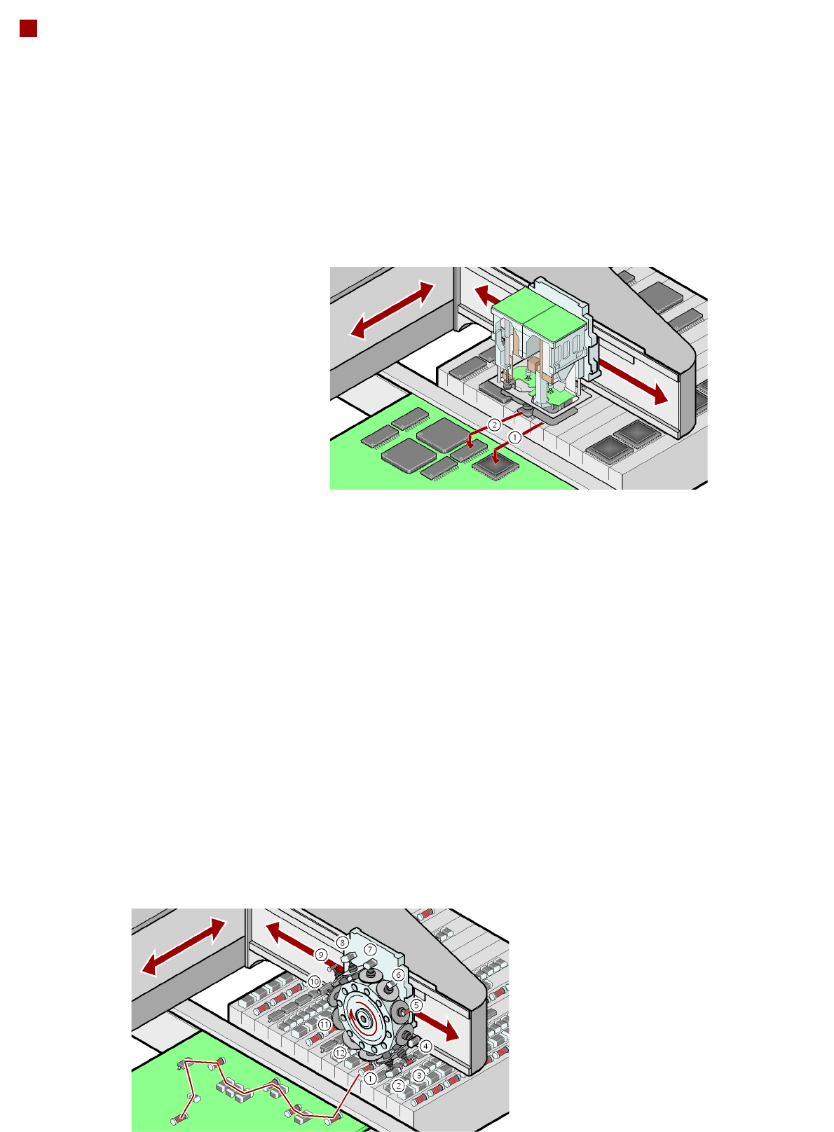
Collect&Place principle
The SIPLACE 12 and 6-noz-
zle Collect&Place heads
work on the Collect&Place
principle. This means that,
within each cycle, 12 or 6
components are picked up
and "collected" by the place-
ment head, are optically cen-
tered on the way to the board
and are rotated into the
required placement angle.
They are then placed gently
and accurately on the PCB.
This principle is particularly
suitable for the high-speed
placement of standard com-
ponents.
Collect&Place principle
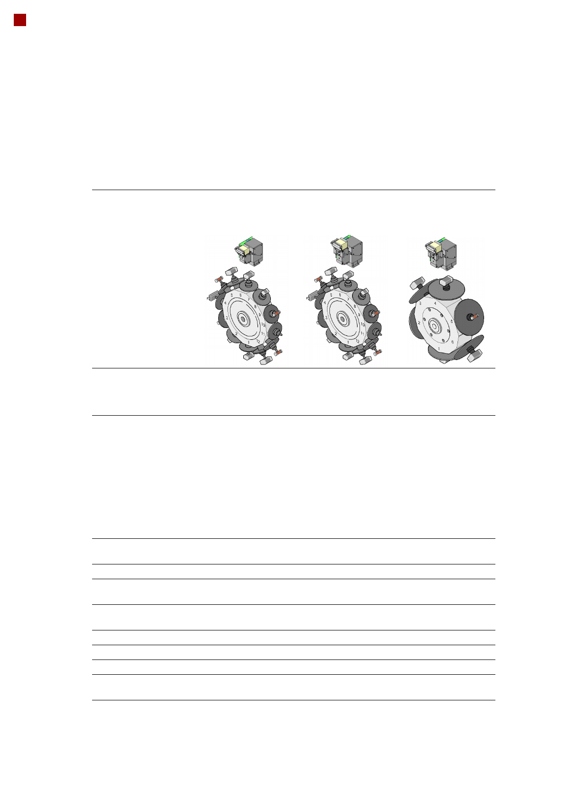
Pick&Place principle
The high-precision SIPLACE
TwinHead, which consists of
two Pick&Place placement
modules of the same design
coupled together, works on
the Pick&Place principle.
Two components are picked
up by the placement head,
optically centered on the way
to the placement position
and rotated into the neces-
sary placement angle. This
principle has proved particu-
larly suitable for fast and
accurate placement of spe-
cial components in the fine
pitch and super-fine pitch
range, and for complex and
heavy components that
require grippers, for
example.
Checking and self-learning
functions
The SIPLACE placement
heads' reliability can be fur-
ther increased with various
checking and self-learning
functions.
• Component sensor
It checks for the presence
of a component at the noz-
zle before and after the
pick-up and placement
process.
• Digital camera on the
placement head
Checks the position of
each component at the
nozzle. Any deviations
from the required pick-up
position are corrected
before placement takes
place.
• Force sensor
Monitors the specified
component set-down forc-
es. With the sensor stop
method, differences in
height during pick-up and
any unevenness of the
PCB surface are compen-
sated during placement.
• Vacuum sensor
Checks whether the com-
ponent was picked up or
set down correctly.
11
Placement Heads
Standard Functions / Options
12-nozzle Collect&Place head 6-nozzle Collect&Place head
Standard-
functions
Camera, vacuum sensor, force
measurement, PCB warpage,
check, individual recording for
each component
Standard
functions
High-resolution camera,
vacuum sensor, force measure-
ment, PCB warpage, check,
individual recording for each
component
Options High-resolution camera, compo-
nent sensor, short nozzle, short
sleeve, nozzle changers, special
nozzles
Options Short nozzle, short sleeve,
nozzle changers, special
nozzles
TwinHead
Standard
functions
Fine-pitch camera, vacuum sen-
sor, force sensor, nozzle
changer, PCB warpage check,
individual recording for each
component
Options Flip-chip camera, special noz-
zles, grippers, coplanarity mod-
ule
12
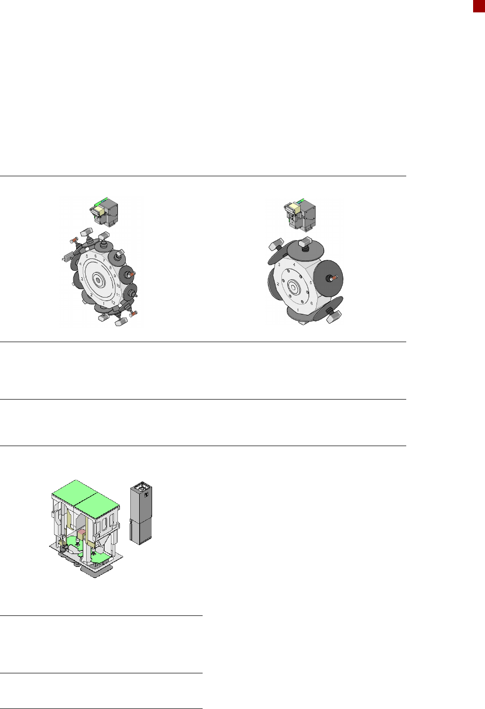
Placement Heads
Collect&Place Heads
12-nozzle
Collect&Place head
CO camera type 28
12-nozzle
Collect&Place head
CO camera type 29
6-nozzle
Collect&Place head
CO camera type 29
Component range
a
a) Please note that the range of components that can be placed is also affected by the pad geometry, cus-
tomer-specific standards, component packaging tolerances and component tolerances
0402 to PLCC44, BGA,
µBGA, flip-chip, TSOP,
QFP, SO to SO32,
DRAM
0201
b
to flip-chip, bare
die, PLCC44, BGA,
µBGA, TSOP, QFP, SO
to SO32, DRAM
b) With 0201 package
0201 to 27 x 27 mm²
Component spec.
max. height
min. lead pitch
min. lead width
min. ball pitch
min. ball diameter
min. dimensions
max. dimensions
max. weight
6 mm
0.5 mm
0.2 mm
0.35 mm
0.2 mm
1.0 x 0.5 mm²
18.7 x 18.7 mm²
2 g
6 mm
0.3 mm
0.15 mm
0.25 mm
0.14 mm
0.6 x 0.3 mm²
18.7 x 18.7 mm²
2 g
8.5 mm
0.3 mm
0.15 mm
0.25 mm
c
0.35 mm
d
0.14 mm
c
0.2 mm
d
0.6 x 0.3 mm²
27 x 27 mm²
5 g
c) For components < 18 x 18 mm²
d) For components 18 x 18 mm²
Programmable set-down
force
2.4 N - 5.0 N 2.4 N - 5.0 N 2.4 N - 5.0 N
Nozzle types 9xx 9xx 8xx, 9xx
X/Y accuracy
e
e) The accuracy value was measured using the vendor-neutral IPC standard
± 45 µm/3
± 60 µm/4
± 41 µm/3
± 55 µm/4
± 45 µm/3
± 60 µm/4
Angular accuracy ± 0.5° / 3
± 0.7° / 4
± 0.5° / 3
± 0.7° / 4
± 0.2° / 3
± 0.3° / 4
Component range 98% 98.5% 99.5%
Component camera type 28 29 29
Illumination levels 5 5 5
Possible illumination
level settings
256
5
256
5
256
5