SIPLACE D3 规格说明书英文版.pdf - 第8页
8 Modular Machine Concept Step 1: Plac ement system with 3 g antries Step 2: Se lection of t he place ment head s 12-nozzle C & P head 6-nozzle C & P he ad TwinHead Step 3: Selectio n of the conveyor Single conve…

7
Machine Performance
This increases machine utili-
zation and reduces waste.
And with respect to the cur-
rent production run, the
SIPLACE vision teaching
station also makes it ex-
tremely simple and fast to
generate component shape
descriptions, even for com-
plex components. The set-up
process starts once you have
optimized the product and
defined all the components in
the programming system.
This is also done externally
and then checked by means
of the barcode and data
transfer. This makes the
product change child's play:
the program and all the data
are sent to the line and the
new production run can start.
It just can't get any faster!
Lowest dpm with set-up
verification, sophisticated
sensors and AOI
The highest machine quality
allows the SIPLACE D3 to
produce the highest product
quality. This is guaranteed by
a number of additional fea-
tures.
Sensors check the presence
and position of the compo-
nents before and after every
pick-up and placement oper-
ation at the placement head.
The digital SIPLACE Vision
System detects the compo-
nents faster and more reli-
ably than the old analog
technology. Finally, with
SIPLACE OS, the SIPLACE
team is offering an AOI
(Automatic Optical Inspec-
tion) device that checks the
products and signals errors
to the placement machine.
This network of tests consid-
erably lowers dpm rates and
increases the first pass yield.
Types of
placement head
12-nozzle Collect&Place head (C&P12)
6-nozzle Collect&Place head (C&P6)
SIPLACE TwinHead (TH)
Please note IPC value [comp./h]
According to the vendor-neutral conditions of the IPC 9850 standard published
by the Association of Connecting Electronics Industries.
SIPLACE Benchmark value [comp./h]
The SIPLACE benchmark value is measured during the machine acceptance
tests. It corresponds to the conditions set out in the SIPLACE scope of service
and supply.
Theoretical maximum output value [comp./h]
The theoretical maximum output value is calculated from the most favorable
conditions for each machine type and setting, and corresponds to the theoreti-
cal conditions normally used in the industry.
Number of gantries 3
Placement area 1 Placement area 2 IPC value Benchmark value Theoretical value
C&P12 / C&P12 C&P12 37,600 40,400 61,000
C&P12 / C&P12 C&P6 33,200 36,200 52,500
C&P12 / C&P12 TH 28,800 31,400 47,000
C&P12/C&P6 C&P6 28,500 30,100 43,500
C&P12/C&P6 TH 24,100 25,300 38,500
C&P12 / TH TH 21,300 23,800 33,500
C&P6 / C&P6 C&P6 25,100 28,100 34,500
C&P6 / C&P6 TH 20,700 23,300 29,500
C&P6 / TH TH 16,900 19,400 24,500
TH / TH TH 11,600 12,500 19,500
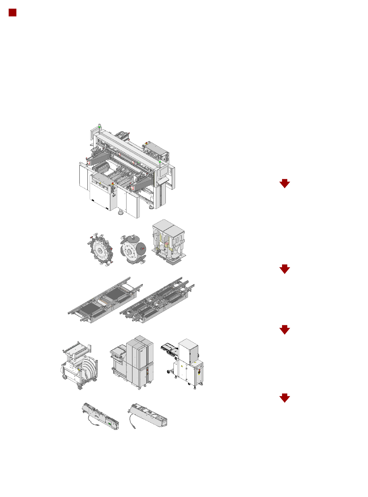
8
Modular Machine Concept
Step 1: Placement system with 3 gantries
Step 2: Selection of the placement heads
12-nozzle C&P head
6-nozzle C&P head
TwinHead
Step 3: Selection of the conveyor
Single conveyor
Flexible dual conveyor
Step 4: Selection of the component
changeover table, MTC, WPC
SIPLACE HF component changeover table
MTC
WPC
Step 5: Selection of the feeder modules
S Tape Feeder Modules
9
Modular Machine Concept
Sample Configuration
NCH1
NCH2
NCH1
C&P/TH
HF
MTC/HF
C&P/TH
NCH2
NCH1
NCH2
NCH1
PA1
PA2
MTC/WPC/HF
HF
C&P/TH
BZ Buffer zone
C&P Collect&Place head
HF SIPLACE HF component changeover table
MTC Matrix Tray Changer
NCH1 Nozzle changer, row 1
NCH2 Nozzle changer, row 2
OP Operator panel
PA1 Placement area 1
PA2 Placement area 2
TH TwinHead
WPC Waffle-pack changer
OP OP
BZ
BZ
BZ