SIPLACE D3 规格说明书英文版.pdf - 第9页
9 Modular Machine Concept Sample Configuration NCH1 NCH2 NCH1 C&P / T H HF MTC/HF C&P/TH NCH2 NCH1 NCH2 NCH1 PA1 PA2 MTC/WPC/HF HF C&P/TH BZ Buffer zone C&P Collect & Place head HF SIPLACE HF componen…
8
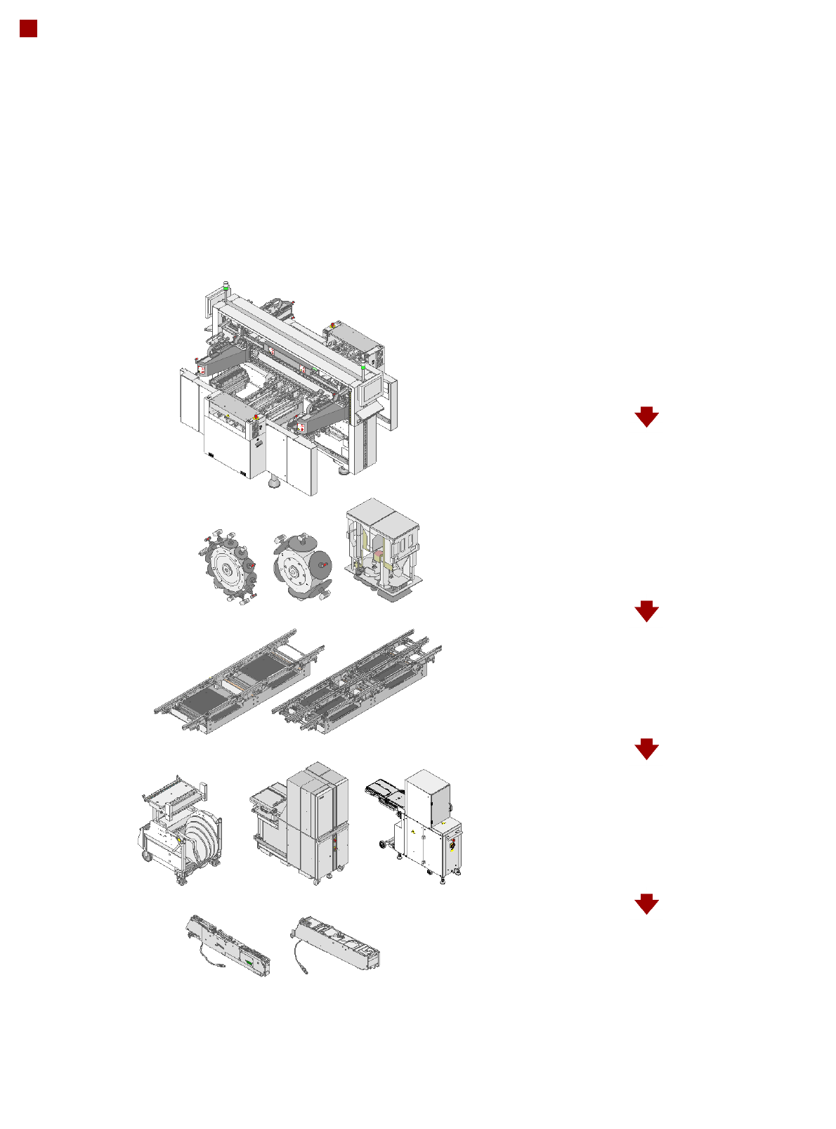
Modular Machine Concept
Step 1: Placement system with 3 gantries
Step 2: Selection of the placement heads
12-nozzle C&P head
6-nozzle C&P head
TwinHead
Step 3: Selection of the conveyor
Single conveyor
Flexible dual conveyor
Step 4: Selection of the component
changeover table, MTC, WPC
SIPLACE HF component changeover table
MTC
WPC
Step 5: Selection of the feeder modules
S Tape Feeder Modules
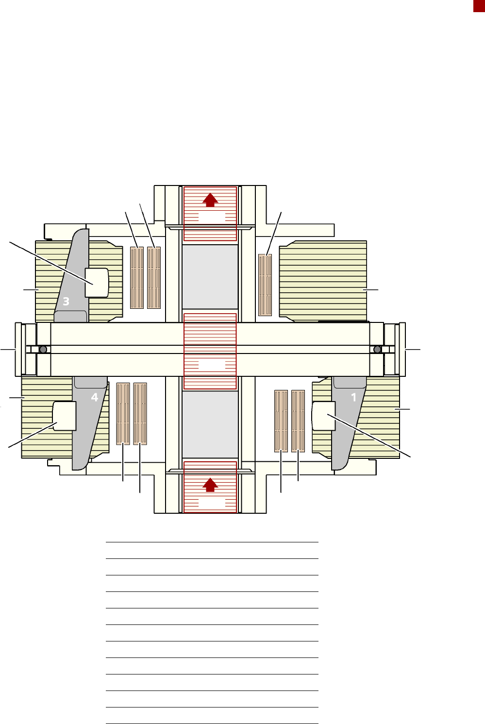
9
Modular Machine Concept
Sample Configuration
NCH1
NCH2
NCH1
C&P/TH
HF
MTC/HF
C&P/TH
NCH2
NCH1
NCH2
NCH1
PA1
PA2
MTC/WPC/HF
HF
C&P/TH
BZ Buffer zone
C&P Collect&Place head
HF SIPLACE HF component changeover table
MTC Matrix Tray Changer
NCH1 Nozzle changer, row 1
NCH2 Nozzle changer, row 2
OP Operator panel
PA1 Placement area 1
PA2 Placement area 2
TH TwinHead
WPC Waffle-pack changer
OP OP
BZ
BZ
BZ
10
Placement Heads
Overview
Head Modularity
The SIPLACE D3 is charac-
terized by maximum flexibil-
ity in the production process.
This flexibility is partly due to
the head modularity of the
placement machine as it
allows different placement
head variants to be config-
ured to suit the production
requirements.
Collect&Place principle
The SIPLACE 12 and 6-noz-
zle Collect&Place heads
work on the Collect&Place
principle. This means that,
within each cycle, 12 or 6
components are picked up
and "collected" by the place-
ment head, are optically cen-
tered on the way to the board
and are rotated into the
required placement angle.
They are then placed gently
and accurately on the PCB.
This principle is particularly
suitable for the high-speed
placement of standard com-
ponents.
Collect&Place principle
Pick&Place principle
The high-precision SIPLACE
TwinHead, which consists of
two Pick&Place placement
modules of the same design
coupled together, works on
the Pick&Place principle.
Two components are picked
up by the placement head,
optically centered on the way
to the placement position
and rotated into the neces-
sary placement angle. This
principle has proved particu-
larly suitable for fast and
accurate placement of spe-
cial components in the fine
pitch and super-fine pitch
range, and for complex and
heavy components that
require grippers, for
example.
Checking and self-learning
functions
The SIPLACE placement
heads' reliability can be fur-
ther increased with various
checking and self-learning
functions.
• Component sensor
It checks for the presence
of a component at the noz-
zle before and after the
pick-up and placement
process.
• Digital camera on the
placement head
Checks the position of
each component at the
nozzle. Any deviations
from the required pick-up
position are corrected
before placement takes
place.
• Force sensor
Monitors the specified
component set-down forc-
es. With the sensor stop
method, differences in
height during pick-up and
any unevenness of the
PCB surface are compen-
sated during placement.
• Vacuum sensor
Checks whether the com-
ponent was picked up or
set down correctly.