00190529-02.pdf - 第25页
SI PLACE 80 F Retrofitting Instructions 1 CPW 20 Nozzle Changer for 1 C Head Edition 11 / 97 Fig . 1.2 Side view of the ICPW 20 nozzle changer • Place the machine spirit level on the base plate of the nozzle changer . Th…
Edition
11
/
97
SIPLACE
80
F
Retrofitting
Instructions
ICPW
20
Nozzle
Changer
for
IC
Head
•
Unscrew
the
two
screws
(
2
x
M
4
x
10
)
holding
the
connector
block
and
the
four
screws
(
4
x
M
6
x
20
)
hol
-
ding
the
support
for
the
coplanarity
module
.
•
Carefully
pull
out
the
cable
for
the
IC
camera
until
you
can
lay
the
support
for
the
copianarity
module
flat
on
the
floor
.
NOTE
All
necessary
work
,
adjustments
and
instructions
on
fitting
the
coplanarity
module
will
be
found
in
the
co
-
planarity
module
retrofitting
instructions
.
•
Remove
the
IC
camera
.
1.6
Fitting
the
ICPW
20
Nozzle
Changer
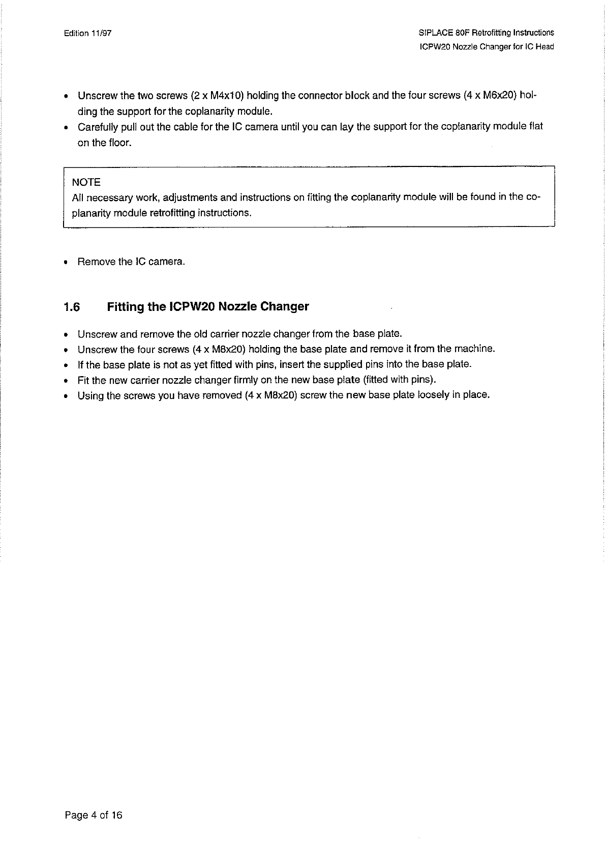
•
Unscrew
and
remove
the
old
carrier
nozzle
changer
from
the
base
plate
.
•
Unscrew
the
four
screws
(
4
x
M
8
x
20
)
holding
the
base
plate
and
remove
it
from
the
machine
.
•
If
the
base
plate
is
not
as
yet
fitted
with
pins
,
insert
the
supplied
pins
into
the
base
plate
.
•
Fit
the
new
carrier
nozzle
changer
firmly
on
the
new
base
plate
(
fitted
with
pins
)
.
•
Using
the
screws
you
have
removed
(
4
x
M
8
x
20
)
screw
the
new
base
plate
loosely
in
place
.
Page
4
of
16
SI
PLACE
80
F
Retrofitting
Instructions
1
CPW
20
Nozzle
Changer
for
1
C
Head
Edition
11
/
97
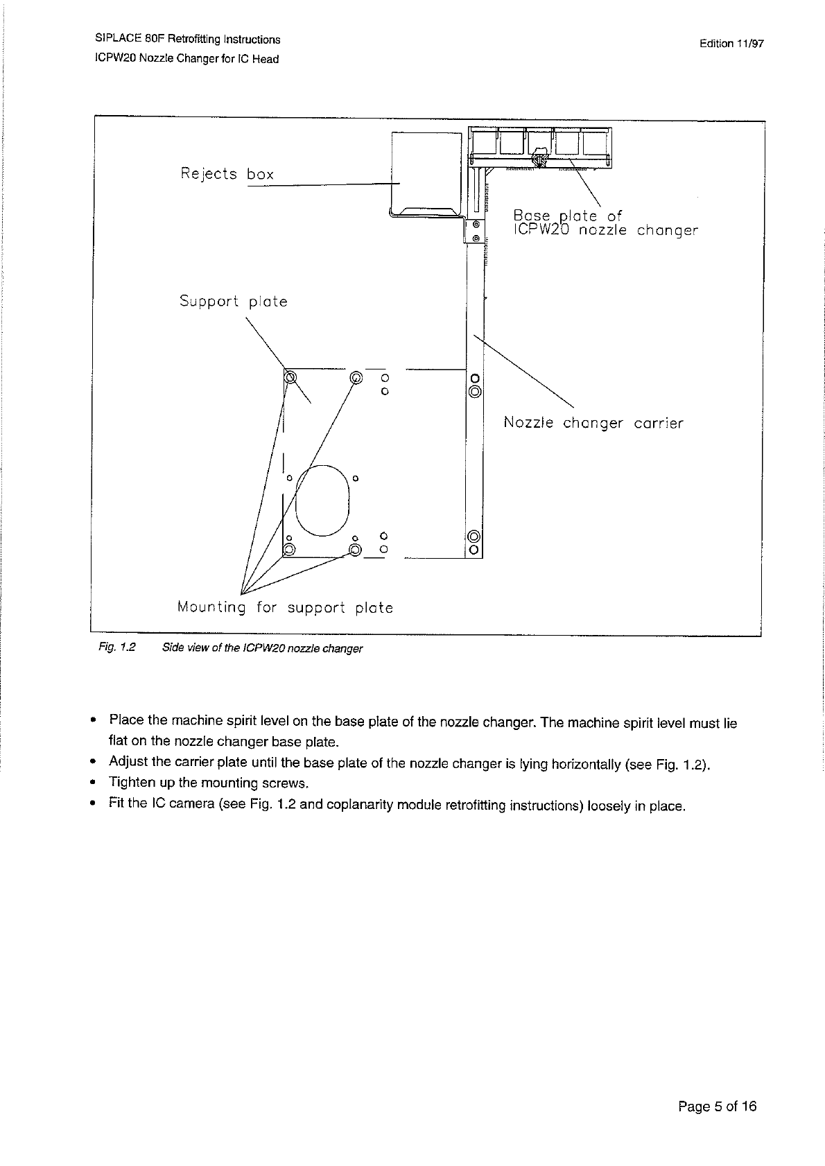
Fig
.
1.2
Side
view
of
the
ICPW
20
nozzle
changer
•
Place
the
machine
spirit
level
on
the
base
plate
of
the
nozzle
changer
.
The
machine
spirit
level
must
lie
flat
on
the
nozzle
changer
base
plate
.
•
Adjust
the
carrier
plate
until
the
base
plate
of
the
nozzle
changer
is
lying
horizontally
(
see
Fig
.
1.2
)
.
•
Tighten
up
the
mounting
screws
,
•
Fit
the
IC
camera
(
see
Fig
.
1.2
and
coplanarity
module
retrofitting
instructions
)
loosely
in
place
.
Page
5
of
16
Edition
11
/
97
SIPLACE
80
F
Retrofitting
Instructions
ICPW
20
Nozzle
Changer
for
IC
Head
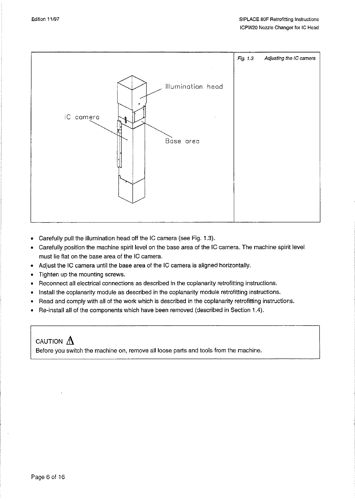
Fig
.
1.3
Adjusting
the
IC
camera
•
Carefully
pull
the
illumination
head
off
the
IC
camera
(
see
Rg
.
1.3
)
.
•
Carefully
position
the
machine
spirit
level
on
the
base
area
of
the
IC
camera
.
The
machine
spirit
level
must
lie
flat
on
the
base
area
of
the
IC
camera
.
•
Adjust
the
IC
camera
until
the
base
area
of
the
IC
camera
is
aligned
horizontally
.
•
Tighten
up
the
mounting
screws
.
•
Reconnect
all
electrical
connections
as
described
in
the
coplanarity
retrofitting
instructions
.
•
Install
the
coplanarity
module
as
described
in
the
coplanarity
module
retrofitting
instructions
.
•
Read
and
comply
with
all
of
the
work
which
is
described
in
the
coplanarity
retrofitting
instructions
.
•
Re
-
install
all
of
the
components
which
have
been
removed
(
described
in
Section
1.4
)
.
A
CAUTION
Before
you
switch
the
machine
on
,
remove
all
loose
parts
and
tools
from
the
machine
.
Page
6
of
16