00190529-02.pdf - 第29页
SI PLACE 80 F Retrofitting Instructions ICPW 20 Nozzle Changer for 1 C Head Edition 11 / 97 1.7 . 4 Real . ma for the ICPW 20 Nozzle Changer • Input the X , y , z and d setpoint positions for the ICPW 20 nozzle changer a…
SI
PLACE
80
F
Retrofitting
Instructions
ICPW
20
Nozzle
Changer
for
1
C
Head
Edition
11
/
97
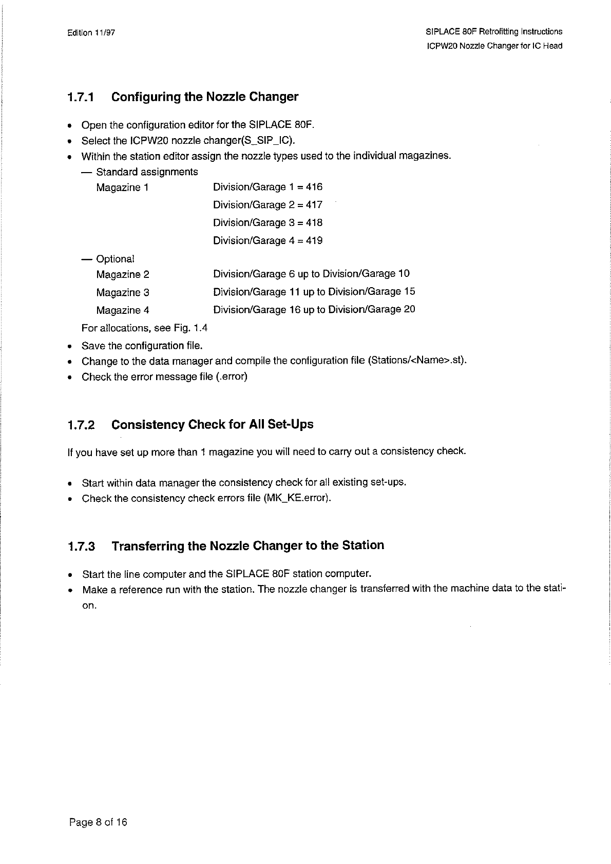
1
-
7
-
1
Configuring
the
Nozzle
Changer
Open
the
configuration
editor
for
the
SIPLACE
80
F
.
Select
the
ICPW
20
nozzle
changer
(
S
_
SIP
」
G
)
.
Within
the
station
editor
assign
the
nozzle
types
used
to
the
individual
magazines
.
—
Standard
assignments
Magazine
1
Division
/
Garage
1
=
416
Division
/
Garage
2
=
417
Division
/
Garage
3
=
418
Division
/
Garage
4
=
419
—
Optional
Magazine
2
Magazine
3
Magazine
4
For
allocations
,
see
Fig
.
1.4
Save
the
configuration
file
.
Change
to
the
data
manager
and
compile
the
configuration
file
(
Stations
/
<
Name
>
.
st
)
.
Check
the
error
message
file
(
.
error
)
Division
/
Garage
6
up
to
Division
/
Garage
10
Division
/
Garage
11
up
to
Division
/
Garage
15
Division
/
Garage
16
up
to
Division
/
Garage
20
1.7
.
2
Consistency
Check
for
All
Set
-
Ups
If
you
have
set
up
more
than
1
magazine
you
will
need
to
carry
out
a
consistency
check
.
•
Start
within
data
manager
the
consistency
check
for
all
existing
set
-
ups
.
•
Check
the
consistency
check
errors
file
(
MK
_
KE
.
error
)
.
1.7
.
3
Transferring
the
Nozzle
Changer
to
the
Station
•
Start
the
line
computer
and
the
SIPLACE
80
F
station
computer
.
•
Make
a
reference
run
with
the
station
.
The
nozzle
changer
is
transferred
with
the
machine
data
to
the
stati
-
on
.
Page
8
of
16
SI
PLACE
80
F
Retrofitting
Instructions
ICPW
20
Nozzle
Changer
for
1
C
Head
Edition
11
/
97
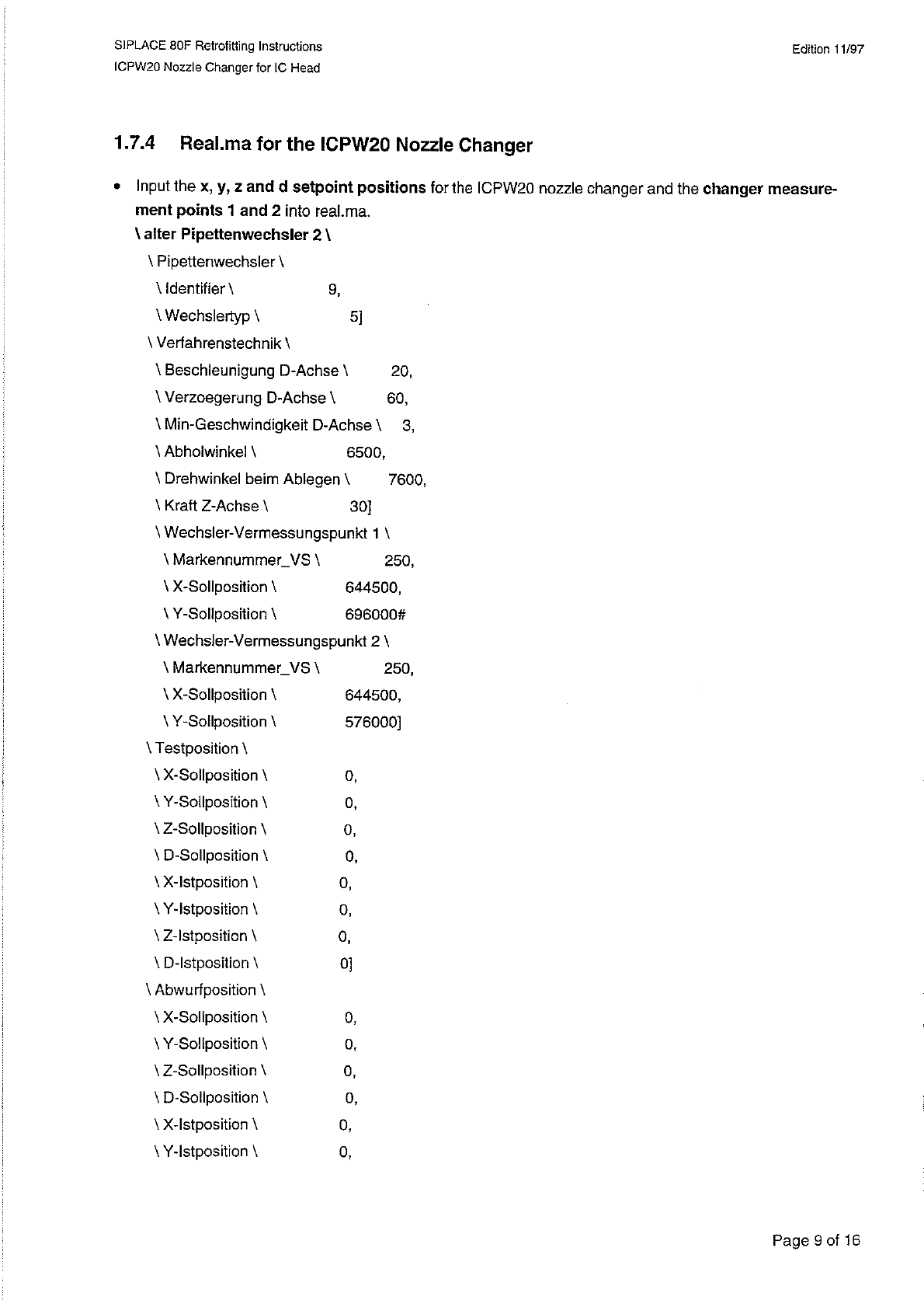
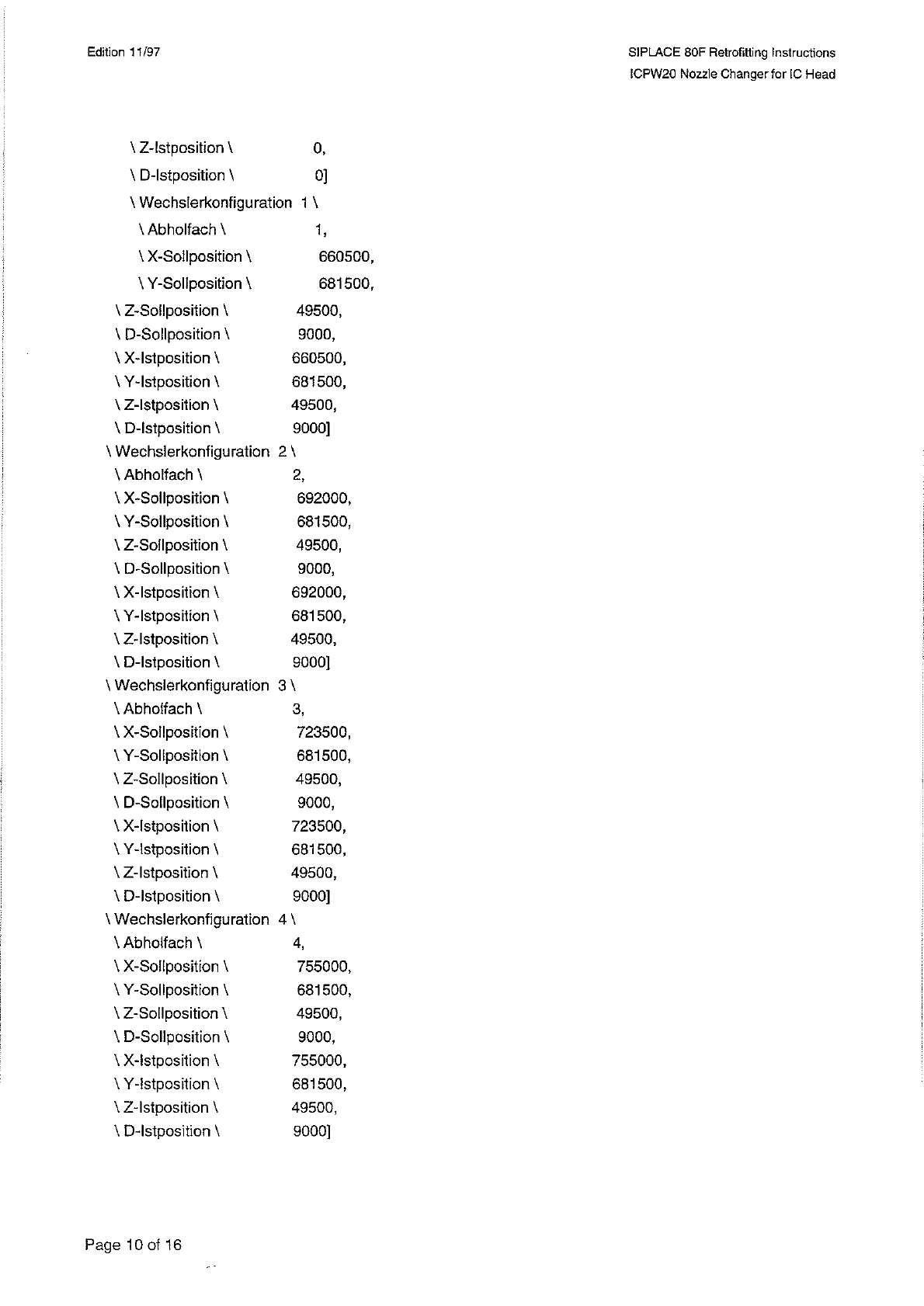
1.7
.
4
Real
.
ma
for
the
ICPW
20
Nozzle
Changer
•
Input
the
X
,
y
,
z
and
d
setpoint
positions
for
the
ICPW
20
nozzle
changer
and
the
changer
measure
-
ment
points
1
and
2
into
real
.
ma
,
\
alter
Pipettenwechsler
2
\
\
Pipettenwechsler
\
\
Identifier
\
\
Wechslertyp
\
\
Verfahrenstechnik
\
\
Beschleunigung
D
-
Achse
\
20
,
\
Verzoegerung
D
-
Achse
\
60
,
\
Min
-
Geschwindigkeit
D
-
Achse
\
3
,
\
Abholwinkel
\
\
Drehwinkel
beim
Ablegen
\
7600
,
\
Kraft
Z
-
Achse
\
\
Wechsler
-
Vermessungspunkt
1
\
\
Markennummer
一
VS
\
\
X
-
Sollposition
\
\
Y
-
Sollposition
\
\
Wechsler
-
Vermessungspunkt
2
\
\
Markennummer
一
VS
\
\
X
-
Sollposition
\
\
Y
-
Sollposition
\
\
Testposition
\
\
X
-
Sollposition
\
\
Y
-
Sollposition
\
\
Z
-
Sollposition
\
\
D
-
Sollposition
\
\
X
-
lstposition
\
\
Y
-
lstposition
\
\
Z
-
lstposition
\
\
D
-
lstposition
\
\
Abwurf
position
\
\
X
-
Sollposition
\
\
Y
-
Sollposition
\
\
Z
-
Soilposition
\
\
D
-
Sollposition
\
\
X
-
lstposition
\
\
Y
-
lstposition
\
9
,
5
]
6500
,
30
]
250
,
644500
,
696000
#
250
,
644500
,
576000
]
0
,
0
,
0
,
0
,
0
,
0
,
0
,
0
]
0
,
0
,
0
,
0
,
0
,
0
,
Page
9
of
16
Edition
11
/
97
SI
PLACE
80
F
Retrofitting
Instructions
ICPW
20
Nozzle
Changer
for
IC
Head
\
Z
-
lstposition
\
\
D
-
lstposition
\
\
Wechslerkonfigu
ration
1
\
Abholfach
\
\
X
-
Soilposition
\
\
Y
-
Sollposition
\
\
Z
-
Sollposition
\
\
D
-
Sollposition
\
\
X
-
lstposition
\
\
Y
-
lstposition
\
\
Z
-
lstposition
\
\
D
-
lstposition
\
\
Wechslerkonfigu
ration
2
\
\
Abholfach
\
\
X
-
Sollposition
\
\
Y
-
Sollposition
\
\
Z
-
Sollposition
\
\
D
-
Sollposition
\
\
X
-
lstposition
\
\
Y
-
lstposition
\
\
Z
-
lstposition
\
\
D
-
lstposition
\
\
Wechslerkonfiguration
3
\
\
Abholfach
\
\
X
-
Soilposition
\
\
Y
-
Soliposition
\
\
Z
-
Sollposition
\
\
D
-
Sollposition
\
\
X
-
lstposition
\
\
Y
-
lstposition
\
\
Z
-
lstposition
\
\
D
-
lstposition
\
\
Wechslerkonfiguration
4
\
\
Abholfach
\
\
X
-
Soilposition
\
\
Y
-
Sollposition
\
\
Z
-
Sollposition
\
\
D
-
Sollposition
\
\
X
-
lstposition
\
\
Y
-
Istposition
\
\
Z
-
lstposition
\
\
D
-
lstposition
\
0
,
0
]
\
660500
,
681500
,
49500
,
9000
,
660500
,
681500
,
49500
,
9000
]
2
,
692000
,
681500
,
49500
,
9000
,
692000
,
681500
,
49500
,
9000
]
3
,
723500
,
681500
,
49500
,
9000
,
723500
,
681500
,
49500
,
9000
]
4
,
755000
,
681500
,
49500
,
9000
,
755000
,
681500
,
49500
,
9000
]
Page
10
of
16