00198536-02_AI_Mixed-Mode_TX2iV1_TX2V2_de_en.pdf - 第116页
4 Appendix 4.1 Excerpts from the Service Manual 116 Assembly Instructions / Montageanleitung SIPLACE TX2i V1 SIPLACE TX2 V2 Option Mixed-Mode 01/2019 4.1.2.6 Replacing the nozzle station Parts, equipment and tools ● Nozz…
4 Appendix
4.1 Excerpts from the Service Manual
Assembly Instructions / Montageanleitung SIPLACE TX2i V1 SIPLACE TX2 V2 Option Mixed-Mode 01/2019 115
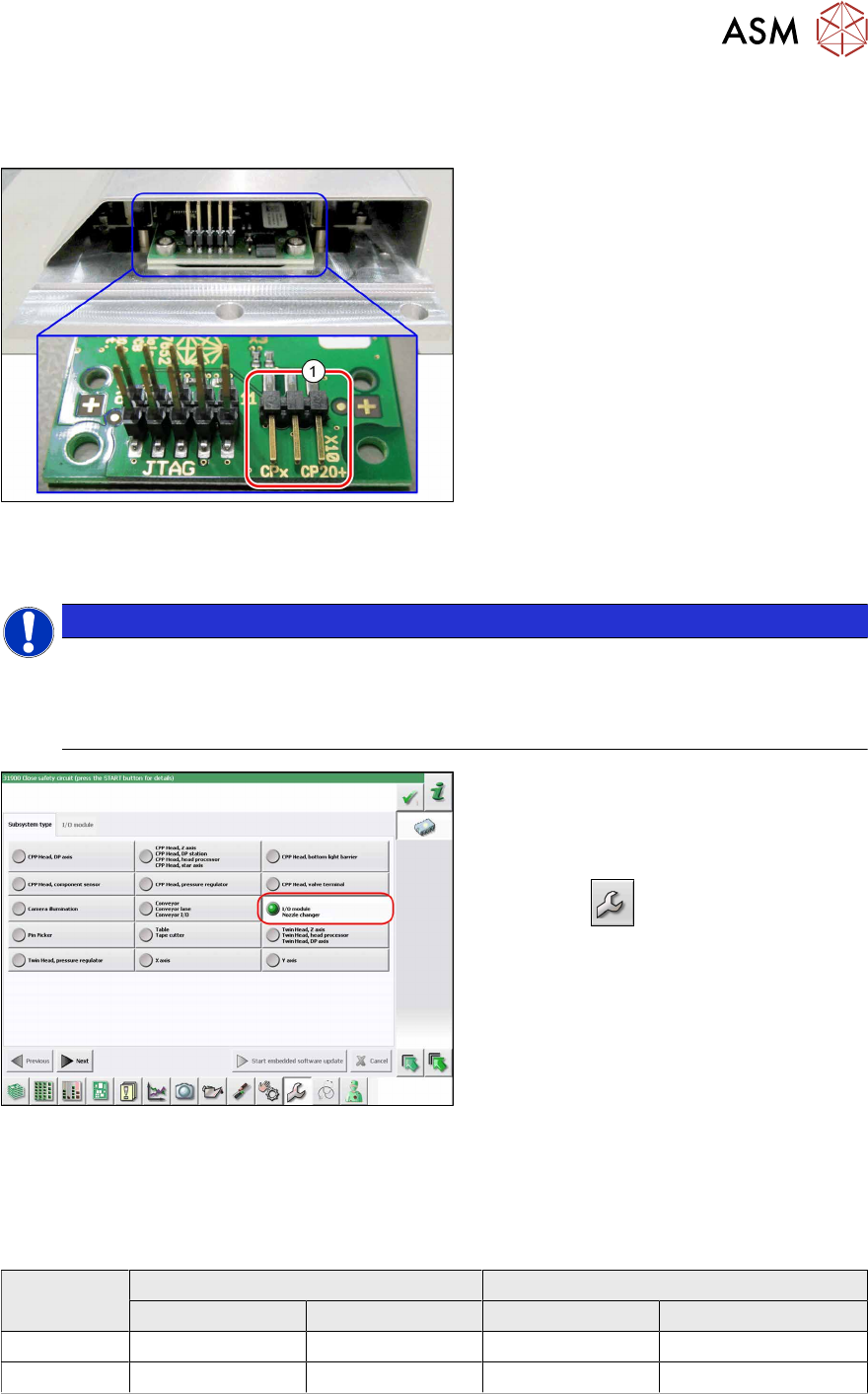
4.1.2.5 Jumpers on the Nozzle Changer
Overview
Fig.64: Jumpers on the Nozzle Changer
1. Jumper X10
The jumper X10 needs to be set at the fol-
lowing nozzle changers:
●
Nozzle changer basic structure CPx/all
assembly - short [03103649-xx]
●
Nozzle changer basic structure CPx/all
assembly - long [03103514-xx]
Preparation
NOTICE
Before installation
Due to the design, this setting must be performed before installation in the machine.
► If the new nozzle changer is being fitted as a spare part in a machine with I/O module
control, you will need to reconnect the jumper to pin 1-2.
Fig.65: Checking the I/A module control
To check whether the machine has I/O mod-
ule control, proceed as follows:
► Switch over to the operator level Ser-
vice.
► Click the
button.
► Click on the Embedded software but-
ton.
► Click the Update subsystem button.
► If an I/O module control is present, you
will see the entry Nozzle Changer at I/
O Module.
Setting
► Set the correct value on the jumper for your head type, software and control method.
Jumper X10
Head SW <= 706.x SW >= 707.x
I/O controller XFCU I/O controller XFCU
CPx, DLM 1-2 1-2 1-2 2-3
C&P20P --- --- --- 2-3 (factory settings)
4 Appendix
4.1 Excerpts from the Service Manual
116 Assembly Instructions / Montageanleitung SIPLACE TX2i V1 SIPLACE TX2 V2 Option Mixed-Mode 01/2019
4.1.2.6 Replacing the nozzle station
Parts, equipment and tools
●
Nozzle station CPx complete / X4iS, XS [03090348-xx]
●
Measuring scale
●
Adjusting plates: support for nozzle reject device [03039514-xx]
Overview
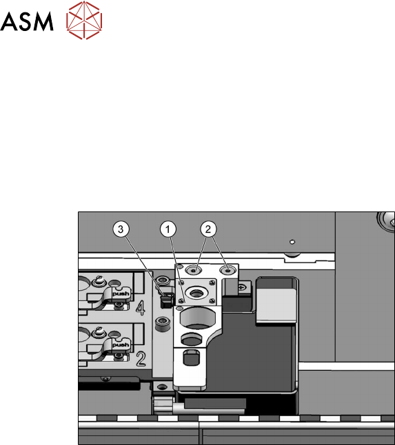
Fig.66: Nozzle station
1. Nozzle station
2. Screws fastening the nozzle station
3. Hose
Removal
► Switch off the machine, disconnect it from the power supply and secure it to prevent
unauthorized reactivation.
1.2 "Preparatory work..." [}77]
► Remove the two screws(2) fastening the nozzle station(1).
► Unplug the hose(3) for nozzle cleaning.
► Remove the nozzle station.
4 Appendix
4.1 Excerpts from the Service Manual
Assembly Instructions / Montageanleitung SIPLACE TX2i V1 SIPLACE TX2 V2 Option Mixed-Mode 01/2019 117
Installation
► Follow the removal instructions in reverse order for installation. Also observe the following
instructions:
CAUTION
Installation instructions
► Check the height of the nozzle station (see below).
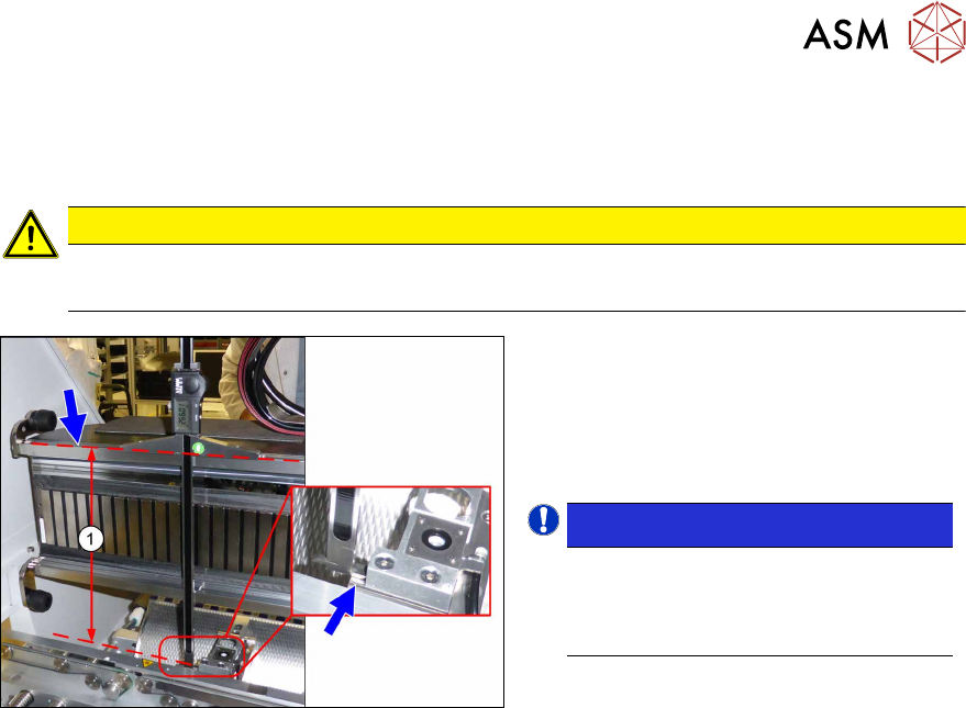
Fig.67: Setting the height of the nozzle station
(taking the standard nozzle station as example)
► The distance(1) between the contact
surface of the nozzle station and the
top edge of the upper guide rail of the
gantry needs to be
266.0+0.1/-0.3mm. You may need to
use shim plates to adjust this.
NOTICE!
Alternatively, you can measure from
the top edge of the lower guide rail of
the gantry. In this case the distance is
105.0+0.1/-0.3mm.
.
See also
2 4.1.2.5 "Jumpers on the Nozzle Changer" [}115]