00198536-02_AI_Mixed-Mode_TX2iV1_TX2V2_de_en.pdf - 第71页
71 Assembly Instructions / Montageanleitung SIPLACE TX2i V1 SIPLACE TX2 V2 Option Mixed-Mode 01/2019 Table of contents Table of contents 1 Introduction .. 73 1.1 Safety Instructions .. 73 1.1.1 Conventions for the us…
4 Anhang
4.2 Stromlaufpläne
70 Assembly Instructions / Montageanleitung SIPLACE TX2i V1 SIPLACE TX2 V2 Option Mixed-Mode 01/2019
► Setzen Sie den Messschieber auf die Oberkante der oberen Linearführung der X‑Achse auf
und messen Sie bis zur Auflagefläche der Pipettenstation. Halten Sie den Messschieber dabei
senkrecht.
► Vergleichen Sie die Messung(1) mit dem Sollwert (siehe Tabelle).
Passen Sie die Höhe ggf. durch Entfernen oder Hinzufügen von PPW-Abstimmplatten an.
Abstand
Standard:
Messung von der Oberkante der oberen Linearführung
268 +0,1/-0,3 mm
Alternativ:
Messung von der Oberkante der unteren Linearführung
107 +0,1/-0,3 mm
VORSICHT
Crashgefahr!
Legen Sie nicht zu viele Abstimmplatten unter.
HINWEIS
Option Mixed-Mode
Im Gegensatz zum Pipettenwechsler wird bei der Option Mixed-Mode die Pipettenstation
nicht tiefer gelegt.
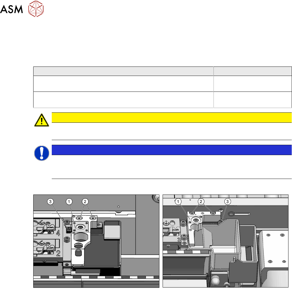
Einbau der Pipettenstation
Abb.93: Pipettenstation für SIPLACE TX1/TX2
Abb.94: Pipettenstation für SIPLACE TX2i V2
► Stecken Sie den Schlauch(3) an die Pipettenstation(1) an.
► Befestigen Sie die Pipettenstation mit zwei Schrauben(2).
► Kalibrieren Sie die Position der Pipettenstation.
Sehen Sie dazu auch...
2 4.1.2.5 "Jumper am Pipettenwechsler" [}53]
4.2 Stromlaufpläne
Weitere Informationen finden Sie in der Wirkschaltplanmappe:
●
Wirkschaltplanmappe SIPLACE TX V1-Serie (bis Nr. 499) [DE+EN:00197933-xx]
●
Wirkschaltplanmappe SIPLACE TX V1-Serie (ab Nr. 500) [DE+EN:00198274-xx]
●
Wirkschaltplanmappe SIPLACE TX V2-Serie [DE+EN: 00198460‑xx]

71Assembly Instructions / Montageanleitung SIPLACE TX2i V1 SIPLACE TX2 V2 Option Mixed-Mode 01/2019
Table of contents
Table of contents
1 Introduction.. 73
1.1 Safety Instructions.. 73
1.1.1 Conventions for the use of safety instructions and symbols.. 73
1.1.2 Safety instructions for working with strong magnetic fields.. 74
1.1.3 Safety instructions for the power supply (with SMPS).. 74
1.1.4 Safety instructions for the compressed air supply.. 76
1.1.5 Safety instructions for work on the cutting device.. 76
1.1.6 Safety instructions for the gantry.. 77
1.1.7 Safety instructions on hazardous materials.. 77
1.2 Preparatory work..... 77
1.3 Other Instructions.. 79
1.3.1 Environmentally-friendly disposal of materials and components.. 79
1.3.2 Use of original accessories and spare parts.. 79
1.3.3 ESD guidelines.. 79
1.3.3.1 What does ESD mean?.. 79
1.3.3.2 Important measures to protect against static charging.. 79
1.3.3.3 Handling ESD modules.. 80
1.3.3.4 Measurements and modifications to ESD modules.. 80
1.3.3.5 Dispatching ESD modules.. 80
1.3.4 Validity of Document.. 80
1.3.5 Release History.. 81
1.4 Staff qualifications and training.. 81
1.5 Abbreviations.. 81
2 Brief description.. 83
2.1 Product description.. 83
2.2 Scope of delivery.. 84
2.3 Tools and equipment required.. 86
2.4 Required Working Time.. 86
2.5 Prerequisites and restrictions.. 86
3 Installation.. 87
3.1 Sealing the Pneumatic Screwed Connections.. 87
3.2 Adapting the hose connections at the pneumatics block.. 87
3.2.1 Removing the cover of the trailing interface.. 88
3.2.2 Creating access to the pneumatics block and modifying the hose connections.. 89
3.2.2.1 Gantry without vacuum hoses (gantry with CPP).. 92
3.2.2.2 Gantry with vacuum hoses(gantry with C&P20x).. 94
3.2.3 Installing the cover of the trailing interface.. 95
3.3 Connecting the vacuum pump.. 96
3.3.1 Installing the vacuum control valve.. 96
3.3.2 Connecting the vacuum pump (SIPLACE TX2i V1).. 97
3.3.3 Connecting the vacuum pump (SIPLACE TX2 V2).. 98
3.4 Converting the COT-i.. 101
3.5 Performing final work.. 104

72 Assembly Instructions / Montageanleitung SIPLACE TX2i V1 SIPLACE TX2 V2 Option Mixed-Mode 01/2019
Table of contents
4 Appendix.. 105
4.1 Excerpts from the Service Manual.. 105
4.1.1 Replacing the trailing interface.. 105
4.1.2 SIPLACE TX V1.. 105
4.1.2.1 Replacing the Trailing Cable Interface.. 105
4.1.2.2 Installation Positions of COT Insert (Table Positions).. 106
4.1.2.3 Replacing the COT-i-i central unit and lifting mechanics.. 107
4.1.2.4 Replacing the Nozzle Changer.. 112
4.1.2.5 Jumpers on the Nozzle Changer.. 115
4.1.2.6 Replacing the nozzle station.. 116
4.1.3 SIPLACE TX V2.. 118
4.1.3.1 Replacing the Trailing Cable Interface.. 118
4.1.3.2 Installation Positions of COT Insert (Table Positions).. 121
4.1.3.3 Replacing the COT‑i.. 122
4.1.3.4 Replacing the Nozzle Changer.. 126
4.1.3.5 Replacing the nozzle station.. 129
4.2 Circuit Diagrams.. 132