00198536-02_AI_Mixed-Mode_TX2iV1_TX2V2_de_en.pdf - 第117页
4 Appendix 4.1 Excerpts from the Service Manual Assembly Instructions / Montageanleitung SIPLACE TX2i V1 SIPLACE TX2 V2 Option Mixed-Mode 01/2019 117 Installation ► Follow the removal instructions in reverse order for in…
4 Appendix
4.1 Excerpts from the Service Manual
116 Assembly Instructions / Montageanleitung SIPLACE TX2i V1 SIPLACE TX2 V2 Option Mixed-Mode 01/2019
4.1.2.6 Replacing the nozzle station
Parts, equipment and tools
●
Nozzle station CPx complete / X4iS, XS [03090348-xx]
●
Measuring scale
●
Adjusting plates: support for nozzle reject device [03039514-xx]
Overview
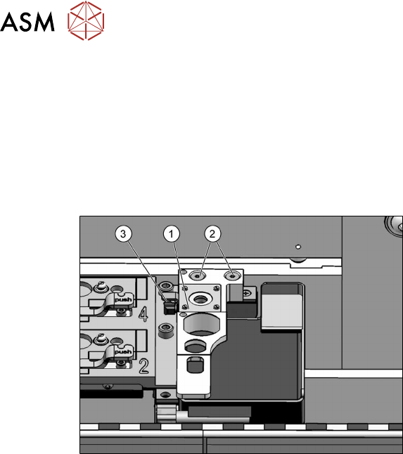
Fig.66: Nozzle station
1. Nozzle station
2. Screws fastening the nozzle station
3. Hose
Removal
► Switch off the machine, disconnect it from the power supply and secure it to prevent
unauthorized reactivation.
1.2 "Preparatory work..." [}77]
► Remove the two screws(2) fastening the nozzle station(1).
► Unplug the hose(3) for nozzle cleaning.
► Remove the nozzle station.
4 Appendix
4.1 Excerpts from the Service Manual
Assembly Instructions / Montageanleitung SIPLACE TX2i V1 SIPLACE TX2 V2 Option Mixed-Mode 01/2019 117
Installation
► Follow the removal instructions in reverse order for installation. Also observe the following
instructions:
CAUTION
Installation instructions
► Check the height of the nozzle station (see below).
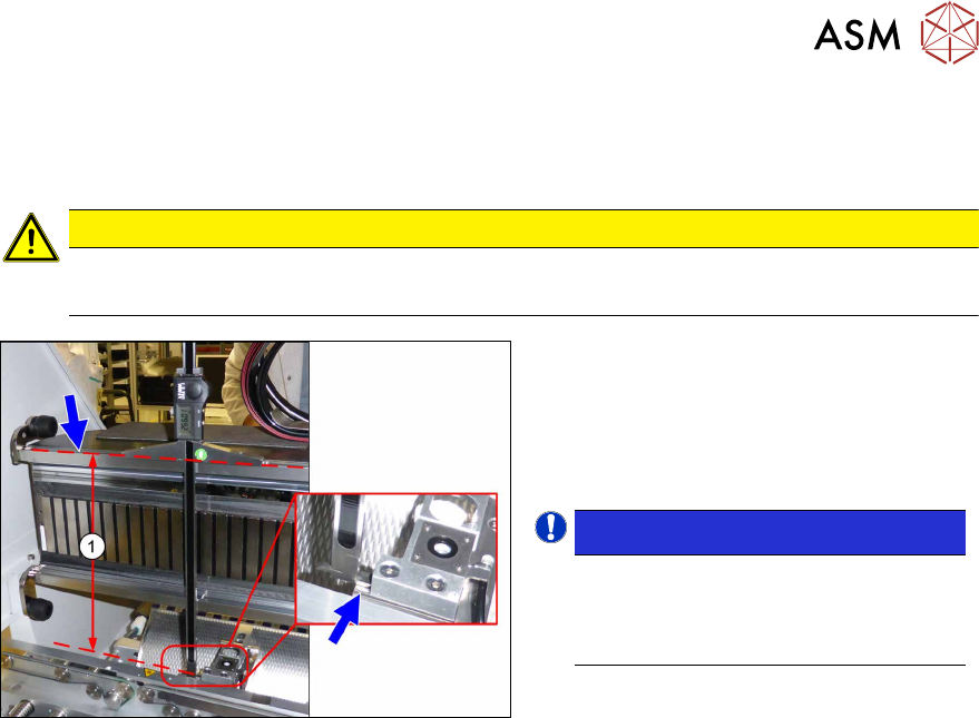
Fig.67: Setting the height of the nozzle station
(taking the standard nozzle station as example)
► The distance(1) between the contact
surface of the nozzle station and the
top edge of the upper guide rail of the
gantry needs to be
266.0+0.1/-0.3mm. You may need to
use shim plates to adjust this.
NOTICE!
Alternatively, you can measure from
the top edge of the lower guide rail of
the gantry. In this case the distance is
105.0+0.1/-0.3mm.
.
See also
2 4.1.2.5 "Jumpers on the Nozzle Changer" [}115]
4 Appendix
4.1 Excerpts from the Service Manual
118 Assembly Instructions / Montageanleitung SIPLACE TX2i V1 SIPLACE TX2 V2 Option Mixed-Mode 01/2019
4.1.3 SIPLACE TX V2
4.1.3.1 Replacing the Trailing Cable Interface
Parts
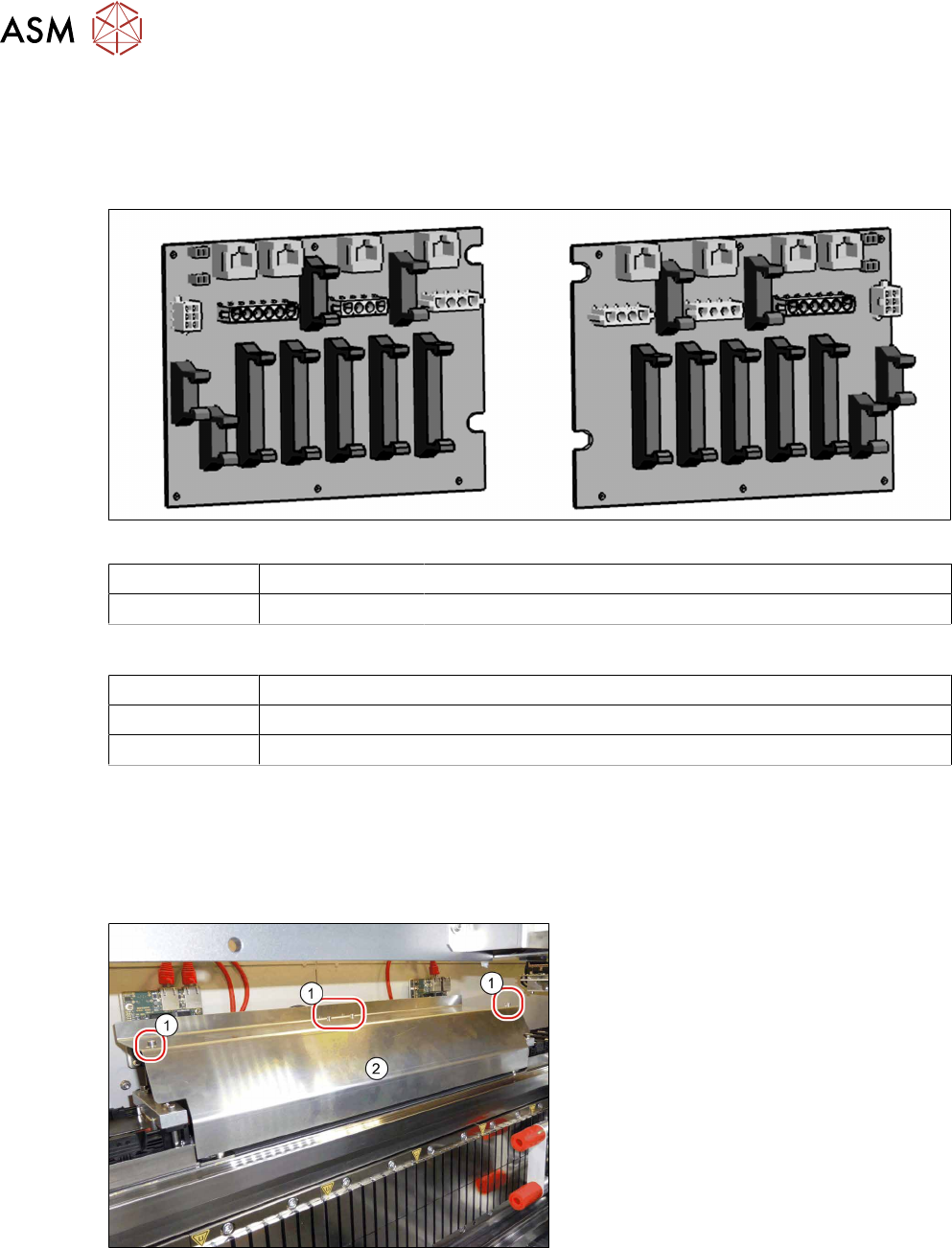
Fig.68: Trailing unit interface gantry 1 and 2
Gantry 1 03138257-xx Trailing unit interface 1 TX V2
Gantry 2 03138259-xx Trailing unit interface 2 TX V2
Equipment and tools
00353832-xx Allen key set
Wire cutters
Cable ties
Removal
► Switch off the machine, disconnect it from the power supply and secure it to prevent
unauthorized reactivation.
1.2 "Preparatory work..." [}77]
► Dismantle the top cover for better access.
Fig.69: Cover
► Loosen the four fastening screws(1)
(Allen key2.5).
► Pull the cover (2) slightly forwards and
then take it up and off.