00198536-02_AI_Mixed-Mode_TX2iV1_TX2V2_de_en.pdf - 第126页
4 Appendix 4.1 Excerpts from the Service Manual 126 Assembly Instructions / Montageanleitung SIPLACE TX2i V1 SIPLACE TX2 V2 Option Mixed-Mode 01/2019 Installation of central unit ► Lift the central unit into the machine.…
4 Appendix
4.1 Excerpts from the Service Manual
Assembly Instructions / Montageanleitung SIPLACE TX2i V1 SIPLACE TX2 V2 Option Mixed-Mode 01/2019 125
Removing the central unit
Before removing the central unit, make sure that the lifting mechanics on the left and right have
been removed (see above).
CAUTION
Heavy machine part!
The COT-i central unit is heavy. To lift it out, you will need to use the mounting tool and a
suitable lifting device (hand-operated crane etc.).
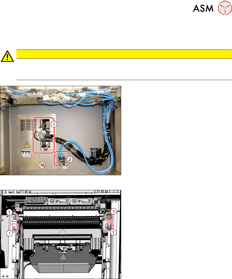
Fig.81: Central unit connections
► Unplug all electrical(1) and pneumatic
connections(2) from the COTi. You
might like to mark their positions to
make clear assignment easier later on.
Fig.82: Central unit fastening screws
► Remove the four fastening screws(1).
► Remove the central unit out of the
machine.
4 Appendix
4.1 Excerpts from the Service Manual
126 Assembly Instructions / Montageanleitung SIPLACE TX2i V1 SIPLACE TX2 V2 Option Mixed-Mode 01/2019
Installation of central unit
► Lift the central unit into the machine. Use a suitable lifting device.
► Reconnect all cables and hoses.
► Move the central unit into its final position on the machine base.
Take care not to damage the cables and hoses.
4.1.3.2 "Installation Positions of COT Insert (Table Positions)" [}121]
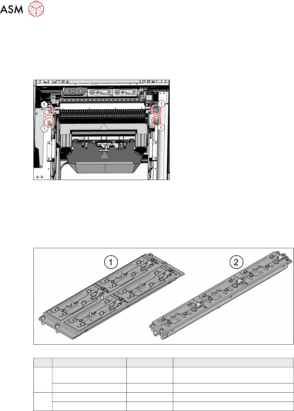
Fig.83: Fixing the central unit (shown from above)
► Insert the four screws(1) and loosely
tighten them.
► Push the central unit as far as possible
away from the conveyor to ensure a
maximum distance to the conveyor
edge.
► Tighten the four screws.
► The further installation of the central unit and lifting mechanics is performed by following the
above instructions in the reverse order.
► Perform necessary calibrations for the location.
4.1.3.4 Replacing the Nozzle Changer
Parts
Fig.84: Nozzle changer
Machine types Item no. Designation
1 SIPLACE TX1/TX2 V2 03103649-xx NC basic structure CPx/all complete assem-
bly short (four magazines)
SIPLACE TX1/TX2 V2 03021079-xx NC shim plate
2 SIPLACE TX2i V2 03129201-xx NC for TX2i V2 (three magazines)
SIPLACE TX2i V2 03133642-xx NC shim plate
4 Appendix
4.1 Excerpts from the Service Manual
Assembly Instructions / Montageanleitung SIPLACE TX2i V1 SIPLACE TX2 V2 Option Mixed-Mode 01/2019 127
Equipment and tools
00353832-xx Allen key set
Set of screwdrivers
03079617-xx Depth measuring gauge (300mm)
Removal
► Switch off the machine, disconnect it from the power supply and secure it to prevent
unauthorized reactivation.
1.2 "Preparatory work..." [}77]
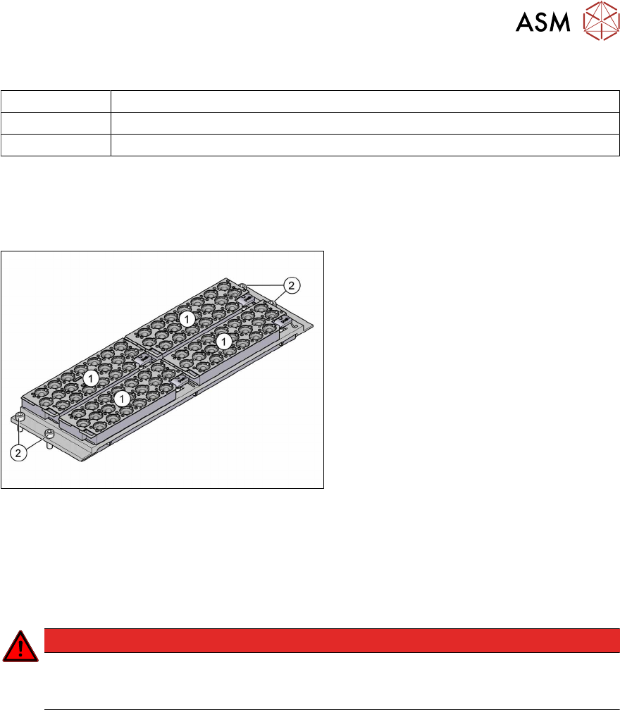
Fig.85: Nozzle changers
► Remove all magazines(1).
► Remove the four fixing screws(2).
► Unplug the nozzles changer from all electrical and pneumatic connections.
► Carefully lift the nozzle changer out of the machine.
Setting the installation height
► Set the correct installation height for the nozzle changer as follows:
DANGER
Strong permanent magnet fields
Observe the safety instructions in section 1.1.2 "Safety instructions for working with strong
magnetic fields" [}74].