00198536-02_AI_Mixed-Mode_TX2iV1_TX2V2_de_en.pdf - 第133页
在线预览 00198536-02_AI_Mixed-Mode_TX2iV1_TX2V2_de_en.pdf PDF 文档。
4 Appendix
4.2 Circuit Diagrams
132 Assembly Instructions / Montageanleitung SIPLACE TX2i V1 SIPLACE TX2 V2 Option Mixed-Mode 01/2019
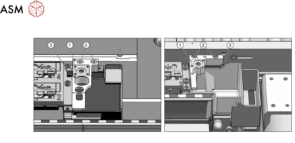
Fitting the nozzle station
Fig.93: Nozzle station for SIPLACE TX1/TX2
Fig.94: Nozzle station for SIPLACE TX2i V2
► Connect the hose(3) to the nozzle changer(1).
► Fasten the nozzle station with two screws(2).
► Calibrate the position of the nozzle station.
See also
2 4.1.2.5 "Jumpers on the Nozzle Changer" [}115]
4.2 Circuit Diagrams
For more information, refer to the circuit diagrams folder:
●
Detailed circuit diagrams folder for SIPLACE TX V1-Series (up to no. 499) [DE+EN:
00197933-xx]
●
Detailed circuit diagrams folder for SIPLACE TX V1-Series (from no. 500) [DE
+EN:00198274-xx]
●
Detailed circuit diagrams SIPLACE TX V2-Series [DE+EN: 00198460-xx]

Item no.:
Artikel-Nr.:
00198536-02 ASM Assembly Systems GmbH & Co. KG
Rupert-Mayer-Strasse 44
81379 Munich
Germany
www.asm-smt.com