00198536-02_AI_Mixed-Mode_TX2iV1_TX2V2_de_en.pdf - 第70页
4 Anhang 4.2 Stromlaufpläne 70 Assembly Instructions / Montageanleitung SIPLACE TX2i V1 SIPLACE TX2 V2 Option Mixed-Mode 01/2019 ► Setzen Sie den Messschieber auf die Oberkante der oberen Linearführung der X‑Achse auf un…
4 Anhang
4.1 Auszüge aus der Serviceanleitung
Assembly Instructions / Montageanleitung SIPLACE TX2i V1 SIPLACE TX2 V2 Option Mixed-Mode 01/2019 69
Ausbau
► Schalten Sie die Maschine aus, trennen Sie diese vom Stromversorgungsnetz und sichern
Sie die Maschine gegen Wiedereinschalten.
1.2 "Was vor Beginn der Arbeiten zu tun ist..." [}11]
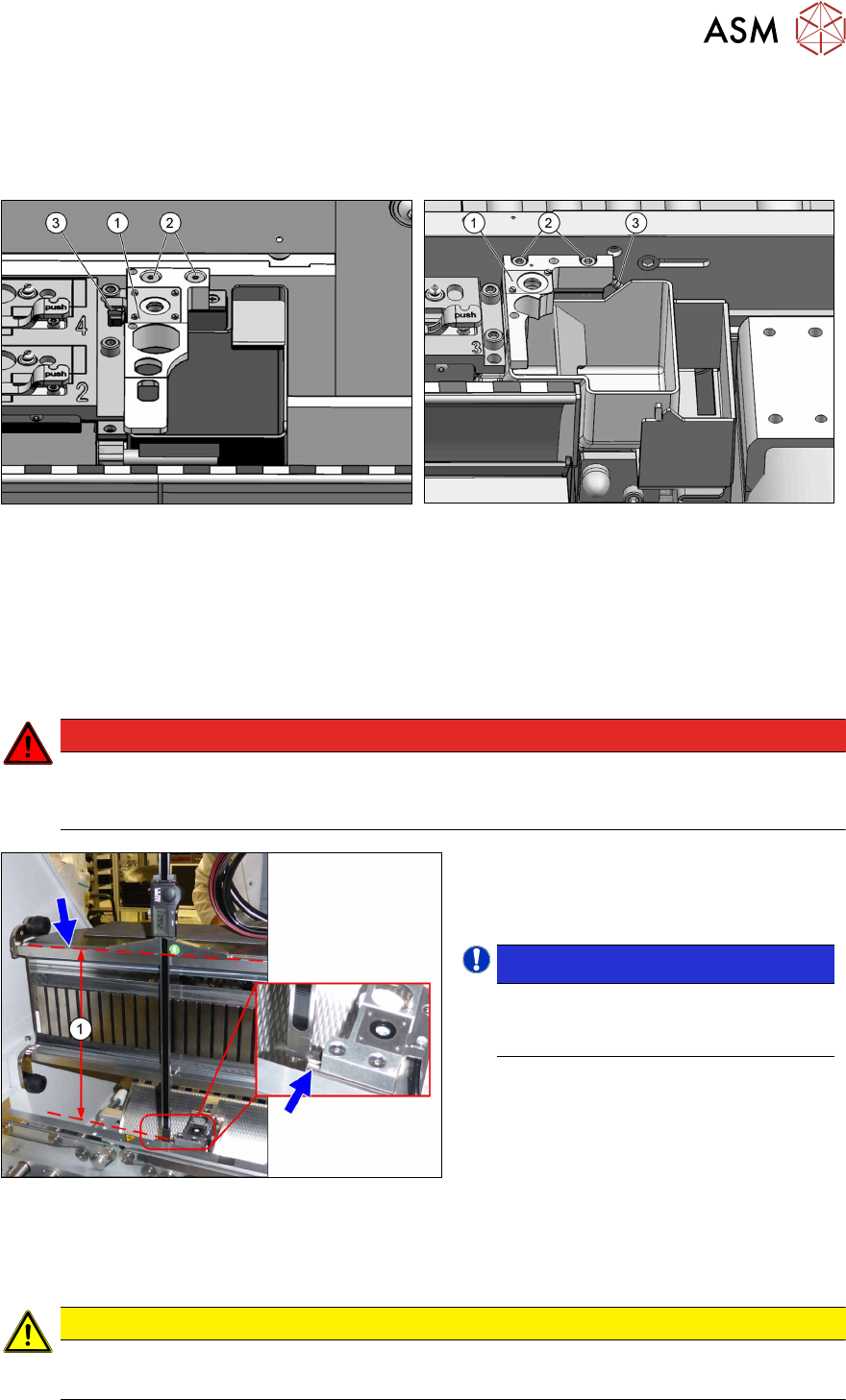
Abb.90: Pipettenstation für SIPLACE TX1/TX2
Abb.91: Pipettenstation für SIPLACE TX2i V2
► Entfernen Sie die beiden Befestigungsschrauben(2) der Pipettenstation(1).
► Stecken Sie den Schlauch(3) ab.
► Entfernen Sie die Pipettenstation.
Einstellung der Einbauhöhe
► Stellen Sie die korrekte Einbauhöhe für die Pipettenstation wie folgt ein:
GEFAHR
Starke Permanentmagnetfelder
Beachten Sie die Sicherheitshinweise in Abschnitt 1.1.2 "Sicherheitshinweise zu Arbeiten
an starken Magnetfeldern" [}8].
Abb.92: Übersicht über den Messvorgang
(am Beispiel der Standard-Pipettenstation)
Übersicht Messvorgang
1. Abstand
HINWEIS!
Alternativ kann auch von der Ober-
kante der unteren Führungsschiene
des Portals gemessen werden.
.
► Achten Sie darauf, dass bei der folgenden Messung die Messschieberspitze für die Innen-
messung nicht die Magnetleiste berührt, da diese sonst verkratzen kann!
VORSICHT
Große Magnetkräfte
► Legen Sie ggf. eine geeignete Kunststoffplatte zwischen Magnet und Messschieber.
4 Anhang
4.2 Stromlaufpläne
70 Assembly Instructions / Montageanleitung SIPLACE TX2i V1 SIPLACE TX2 V2 Option Mixed-Mode 01/2019
► Setzen Sie den Messschieber auf die Oberkante der oberen Linearführung der X‑Achse auf
und messen Sie bis zur Auflagefläche der Pipettenstation. Halten Sie den Messschieber dabei
senkrecht.
► Vergleichen Sie die Messung(1) mit dem Sollwert (siehe Tabelle).
Passen Sie die Höhe ggf. durch Entfernen oder Hinzufügen von PPW-Abstimmplatten an.
Abstand
Standard:
Messung von der Oberkante der oberen Linearführung
268 +0,1/-0,3 mm
Alternativ:
Messung von der Oberkante der unteren Linearführung
107 +0,1/-0,3 mm
VORSICHT
Crashgefahr!
Legen Sie nicht zu viele Abstimmplatten unter.
HINWEIS
Option Mixed-Mode
Im Gegensatz zum Pipettenwechsler wird bei der Option Mixed-Mode die Pipettenstation
nicht tiefer gelegt.
Einbau der Pipettenstation
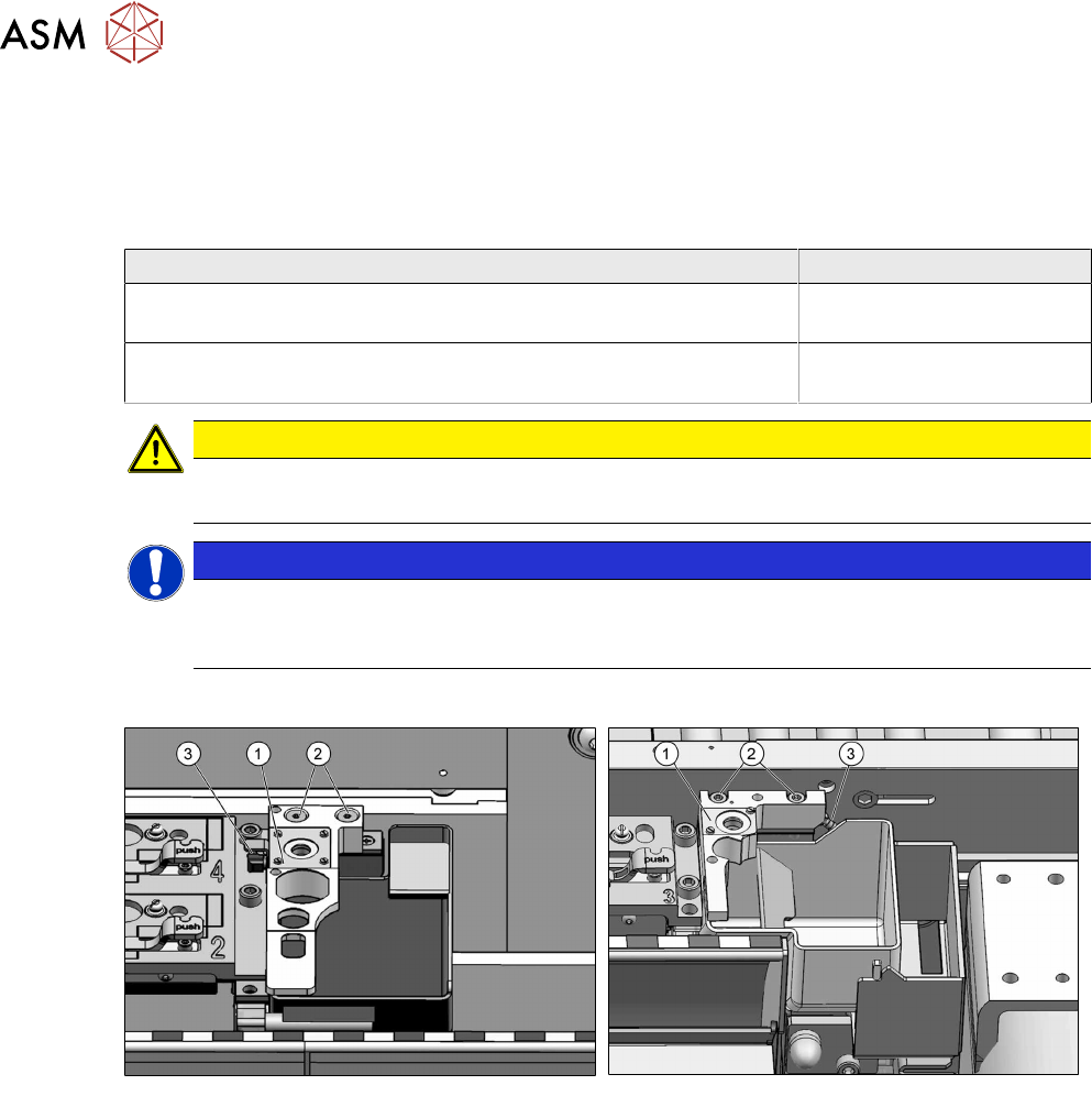
Abb.93: Pipettenstation für SIPLACE TX1/TX2
Abb.94: Pipettenstation für SIPLACE TX2i V2
► Stecken Sie den Schlauch(3) an die Pipettenstation(1) an.
► Befestigen Sie die Pipettenstation mit zwei Schrauben(2).
► Kalibrieren Sie die Position der Pipettenstation.
Sehen Sie dazu auch...
2 4.1.2.5 "Jumper am Pipettenwechsler" [}53]
4.2 Stromlaufpläne
Weitere Informationen finden Sie in der Wirkschaltplanmappe:
●
Wirkschaltplanmappe SIPLACE TX V1-Serie (bis Nr. 499) [DE+EN:00197933-xx]
●
Wirkschaltplanmappe SIPLACE TX V1-Serie (ab Nr. 500) [DE+EN:00198274-xx]
●
Wirkschaltplanmappe SIPLACE TX V2-Serie [DE+EN: 00198460‑xx]

71Assembly Instructions / Montageanleitung SIPLACE TX2i V1 SIPLACE TX2 V2 Option Mixed-Mode 01/2019
Table of contents
Table of contents
1 Introduction.. 73
1.1 Safety Instructions.. 73
1.1.1 Conventions for the use of safety instructions and symbols.. 73
1.1.2 Safety instructions for working with strong magnetic fields.. 74
1.1.3 Safety instructions for the power supply (with SMPS).. 74
1.1.4 Safety instructions for the compressed air supply.. 76
1.1.5 Safety instructions for work on the cutting device.. 76
1.1.6 Safety instructions for the gantry.. 77
1.1.7 Safety instructions on hazardous materials.. 77
1.2 Preparatory work..... 77
1.3 Other Instructions.. 79
1.3.1 Environmentally-friendly disposal of materials and components.. 79
1.3.2 Use of original accessories and spare parts.. 79
1.3.3 ESD guidelines.. 79
1.3.3.1 What does ESD mean?.. 79
1.3.3.2 Important measures to protect against static charging.. 79
1.3.3.3 Handling ESD modules.. 80
1.3.3.4 Measurements and modifications to ESD modules.. 80
1.3.3.5 Dispatching ESD modules.. 80
1.3.4 Validity of Document.. 80
1.3.5 Release History.. 81
1.4 Staff qualifications and training.. 81
1.5 Abbreviations.. 81
2 Brief description.. 83
2.1 Product description.. 83
2.2 Scope of delivery.. 84
2.3 Tools and equipment required.. 86
2.4 Required Working Time.. 86
2.5 Prerequisites and restrictions.. 86
3 Installation.. 87
3.1 Sealing the Pneumatic Screwed Connections.. 87
3.2 Adapting the hose connections at the pneumatics block.. 87
3.2.1 Removing the cover of the trailing interface.. 88
3.2.2 Creating access to the pneumatics block and modifying the hose connections.. 89
3.2.2.1 Gantry without vacuum hoses (gantry with CPP).. 92
3.2.2.2 Gantry with vacuum hoses(gantry with C&P20x).. 94
3.2.3 Installing the cover of the trailing interface.. 95
3.3 Connecting the vacuum pump.. 96
3.3.1 Installing the vacuum control valve.. 96
3.3.2 Connecting the vacuum pump (SIPLACE TX2i V1).. 97
3.3.3 Connecting the vacuum pump (SIPLACE TX2 V2).. 98
3.4 Converting the COT-i.. 101
3.5 Performing final work.. 104