SIPLACE S-23 HM User Manual.pdf - 第11页
11 Menu control of the machine The menu c ontrol and the user inter face of th e machine are based on the Microsoft W indows standa rd. Y ou can initia te actions in the indivi dual menus by u sing – function ke ys F1 to…
10
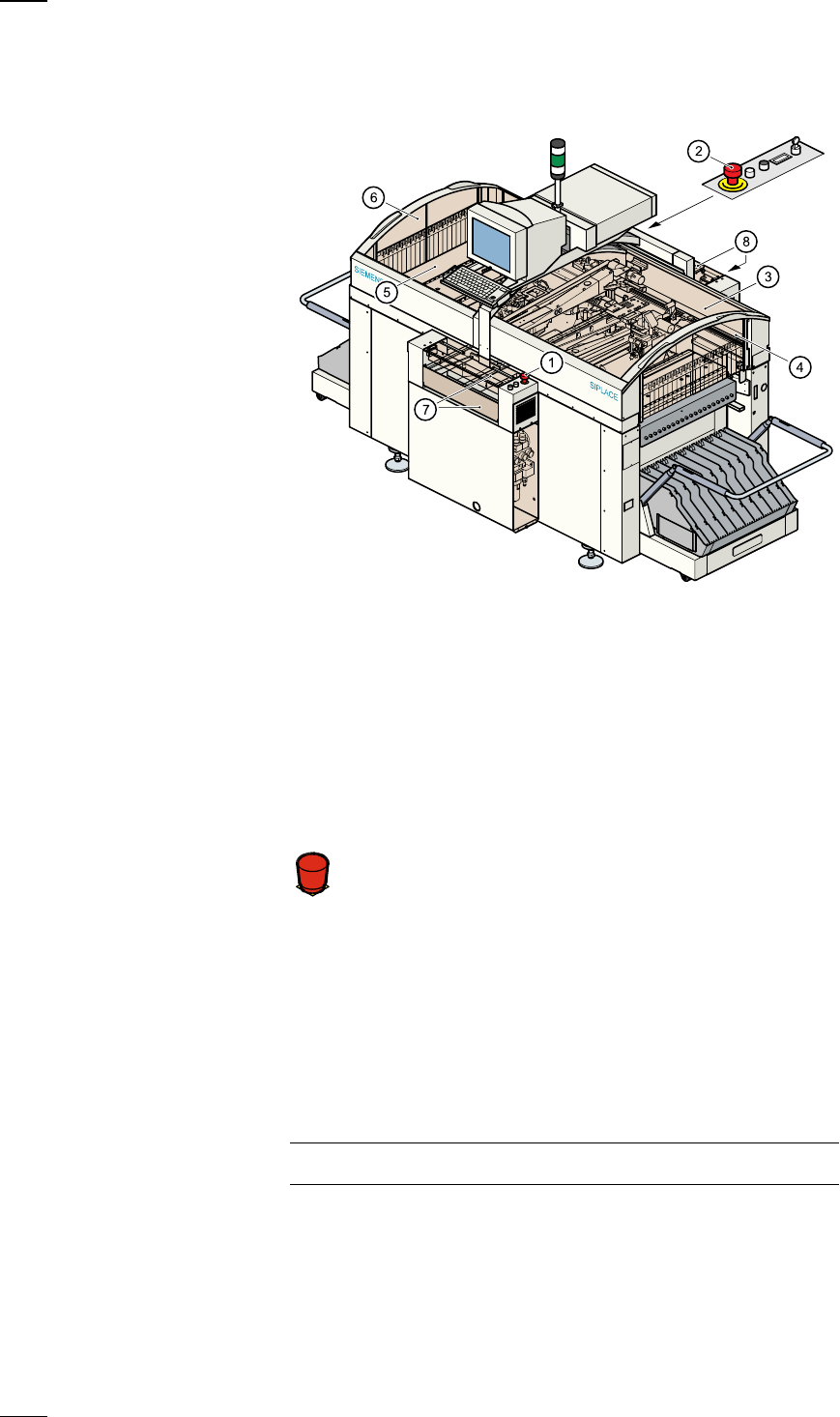
Safety devices
Emergency stop mushroom-head push-buttons
If serious problems occur:
The placement system will stop immediately. Attempt to
eliminate the problem. If this is not possible, call the line
engineer.
Continue processing
● Turn the emergency stop mushroom-head push-button to the left to
release it.
● Press the Start button.
Protective covers
Make sure that all covers are closed when the machine is operating. As
soon as a cover is opened, the machine will stop and an error message of
the following type may be displayed during placement:
General error: 270 PCB interrupted due to EMERGENCY STOP
Transp.: 1 DEV:1 #E:1
● Close the covers and press the Start button.
a
Emergency stop mushroom-head push-button, input side
s
Emergency stop mushroom-head push-button, output side
d
Protective cover, right-hand side
f
Protective glass disks, right-hand side
g
Protective cover, left-hand side
h
Protective glass disks, left-hand side
j
Cover and guard on the input belt
k
Cover and guard on the output belt
Á
F
11
Menu control of the machine
The menu control and the user interface of the machine are based on the
Microsoft Windows standard. You can initiate actions in the individual
menus by using
– function keys F1 to F12 on the keyboard,
– the trackball and the left-hand mouse button or
– the touchscreen.
– You can open pull-downs and their submenus by pressing the Alt-key in
combination with a ’hot key.
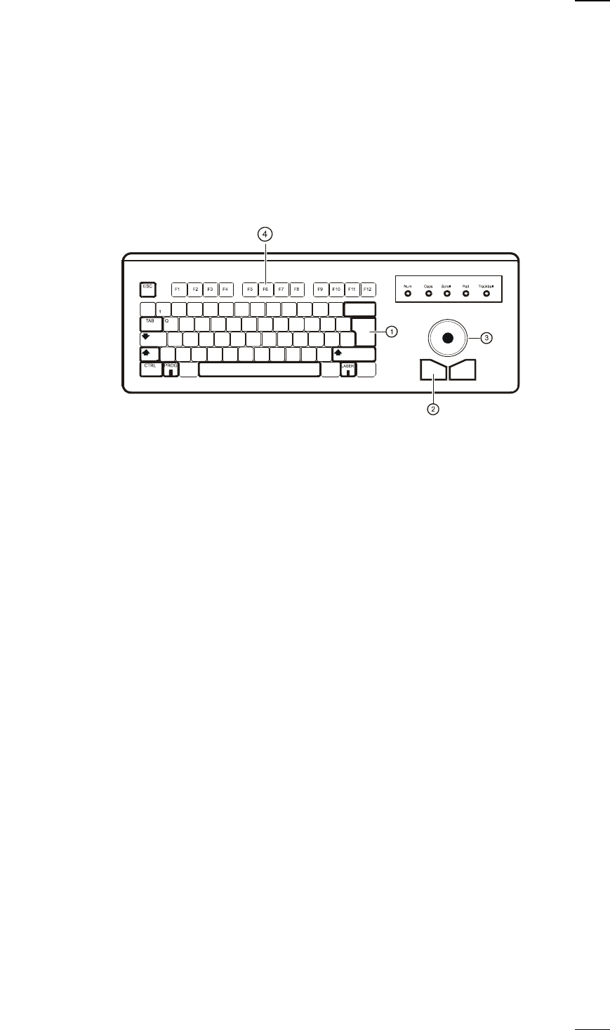
Keyboard with integrated mouse (trackball)
IBM-compatible
keyboard with
German
character set
a
Return key
s
Left-hand mouse button
d
Trackball
f
Function keys F1 to F12
Touchscreen
As an alternative to the trackball you can position the mouse pointer on
the screen and operate it by touching the screen with your finger.
12
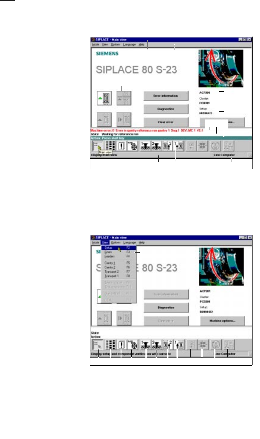
User Interface
Main View - Layout and Explanation of the Symbols
Main View - Submenus
a Indicates the current menu k Error message line
s Menu line with pull-down menus l Status display
d Buttons for user actions ; Operator actions
f Button for calling submenus A Information line for menus
g Job name S Icons with bubble help text
h File name of loaded cluster D Machine operating mode
j File name of loaded setup
a Main View (F1) k SF PCB transport 1 (F8)
s Display setup (F2) l Teach and test PCB fiducial (F9)
d Display errors (F3) ; Measure cmp and change GF data (F10)
f Component feeder systems (F4) A SITEST(F11)
g SF gantry 1 (F5) S GEM status (F12), option
h SF gantry 2 (F6) D Pull-down menu
j SF PCB transport 2 (F7), option
s
df
g
j
A D
a
S
h
kl;
a sdf gh jk l ; AS
D