SIPLACE S-23 HM User Manual.pdf - 第9页
9 Machine Areas The figure below pro vides a diagr ammatic o verview of th e individual ar eas of a SIPLA CE S-23 HM placement station. The terms u sed in th e figure to de scribe the se areas are also used in t he texts…

8
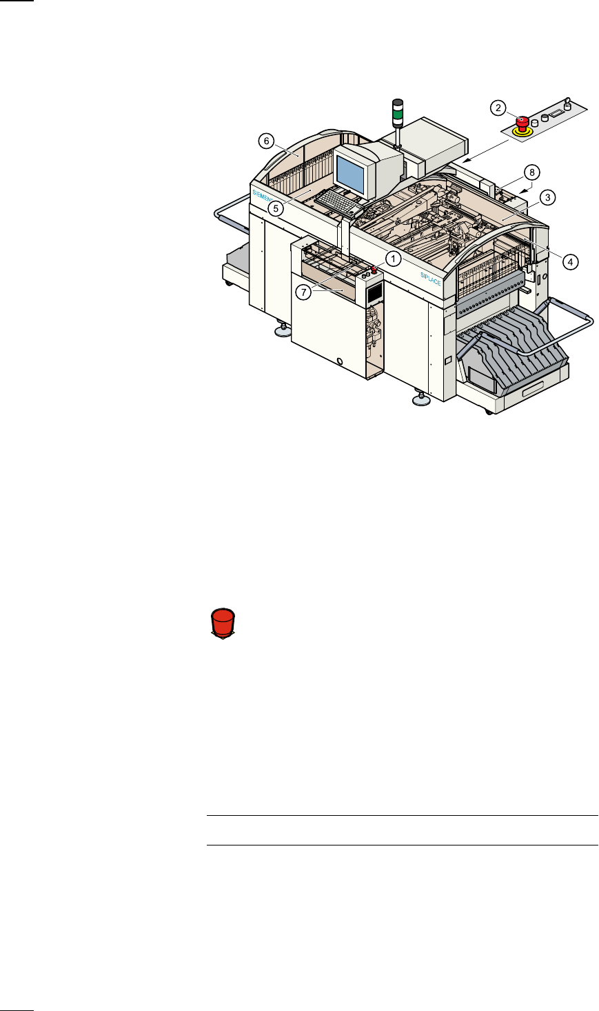
Component barcode reader (option)
There is a compartment for a Datalogic DL 910 component barcode
reader between the keyboard and the screen. The barcode reader
enables the components to be set up and topped up quickly and reliably.
Main fault indicator
The sequence of colours of the indicator lamp is white (L1) - green (L2) -
white (L3). It signals different operating statuses and faults on the place-
ment system.
Functional description of the main fault indicator
Main fault indicator
General operating statuses
–
Operating status lamp (green) on continuously
The placement system is in service
–
Operating status lamp (green) flashes
The placement system is waiting for a PCB on the input belt or the place-
ment system is waiting until the output belt is free.
–
Top white fault indicator lamp L1 flashes
One or more tracks are empty on the right-hand side of the placement
system. The placement system continues to place any remaining compo-
nents.
–
Bottom white fault indicator lamp L3 flashes
One or more tracks are empty on the left-hand side of the placement sys-
tem. The placement system continues to place any remaining compo-
nents
–
Top white fault indicator lamp (L1) on continuously - green operating sta-
tus lamp (L2) off
An error has occurred on the right-hand side of the placement system ->
the placement system has stopped.
–
Bottom white fault indicator lamp (L3) on continuously - green operating
status lamp (L2) off
An error has occurred on the left-hand side of the placement system ->
the placement system has stopped.
–
Both white fault indicator lamps (L1 and L3) on continuously - green oper-
ating status lamp off
An error has occurred that affects the entire placement system -> the
placement system has stopped.
L1: Fault indicator lamp (white)
L2: Operating status lamp (green)
L3: Fault indicator lamp (white)
9
Machine Areas
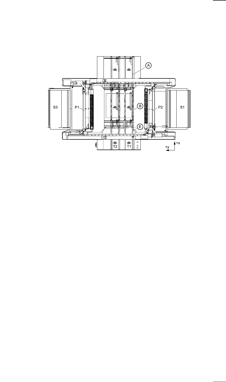
The figure below provides a diagrammatic overview of the individual areas
of a SIPLACE S-23 HM placement station.
The terms used in the figure to describe these areas are also used in the
texts in the user interface and in the User Manual.
The PCB conveyor is divided into the following sections:
– Input conveyor
– Processing conveyor
– Output conveyor
A Output conveyor
E Input conveyor
B Processing conveyor
P1 Gantry 1
P2 Gantry 2
S1 Location 1
S3 Location 3
T1 Conveyor track 1
T2 Conveyor track 2 (twin conveyor option)
10
Safety devices
Emergency stop mushroom-head push-buttons
If serious problems occur:
The placement system will stop immediately. Attempt to
eliminate the problem. If this is not possible, call the line
engineer.
Continue processing
● Turn the emergency stop mushroom-head push-button to the left to
release it.
● Press the Start button.
Protective covers
Make sure that all covers are closed when the machine is operating. As
soon as a cover is opened, the machine will stop and an error message of
the following type may be displayed during placement:
General error: 270 PCB interrupted due to EMERGENCY STOP
Transp.: 1 DEV:1 #E:1
● Close the covers and press the Start button.
a
Emergency stop mushroom-head push-button, input side
s
Emergency stop mushroom-head push-button, output side
d
Protective cover, right-hand side
f
Protective glass disks, right-hand side
g
Protective cover, left-hand side
h
Protective glass disks, left-hand side
j
Cover and guard on the input belt
k
Cover and guard on the output belt
Á
F