SIPLACE S-23 HM User Manual.pdf - 第25页
25 ’Single functions - Gantries 1/2’ menu ↑ UM 5 .2 The Sin gle func tion menu for gantries 1 and 2 are id entical. Only personn el with the correspondin g training and qualifi- cations are permitted to access the Single…
24
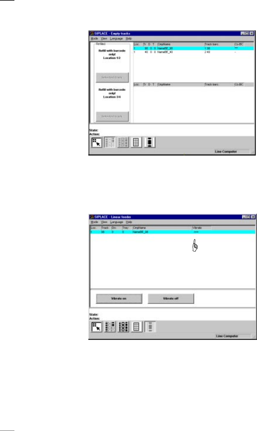
’Display empty tracks with component verification’
↑ UM 4.3.1 If the Component verification with barcode option has been configured
and activated, the following menu will appear:
Within this menu, locations 1 to 4 or individual tracks which have been
given a barcode
cannot
be set to full. Apart from displaying the empty
tracks, this menu also allows to individually set to full those empty tracks
which have not been provided with a barcode. Tracks which do not have a
component barcode are indicated by a dash in the CO-BC column. The
Selected track button is activated here.
’Display linear feeder and vibrate’ menu
When you have filled a linear feeder, you can use this menu to select it
and turn vibration on.
● Select the linear feeder from the list.
● Click on the Vibrate on button. The arrow in the Vibrate column shows that
the module is being vibrated.
● You can stop vibration by clicking on the Vibrate off button.
↑ UM 4.3.3
25
’Single functions - Gantries 1/2’ menu
↑ UM 5.2 The Single function menu for gantries 1 and 2 are identical.
Only personnel with the corresponding training and qualifi-
cations are permitted to access the Single functions Gantry X (X = 1, 2)
menu since improper treatment of the machine may result in serious phys-
ical injury and considerable damage to property.
The Single functions Gantry X menu has the following submenus:
– Gantry functions
– Revolver head functions
– Vacuum test revolver head
– Nozzle offset revolver head
– Nozzle configuration
– Nozzle-changer configuration revolver head (if this option has been
installed and configured)
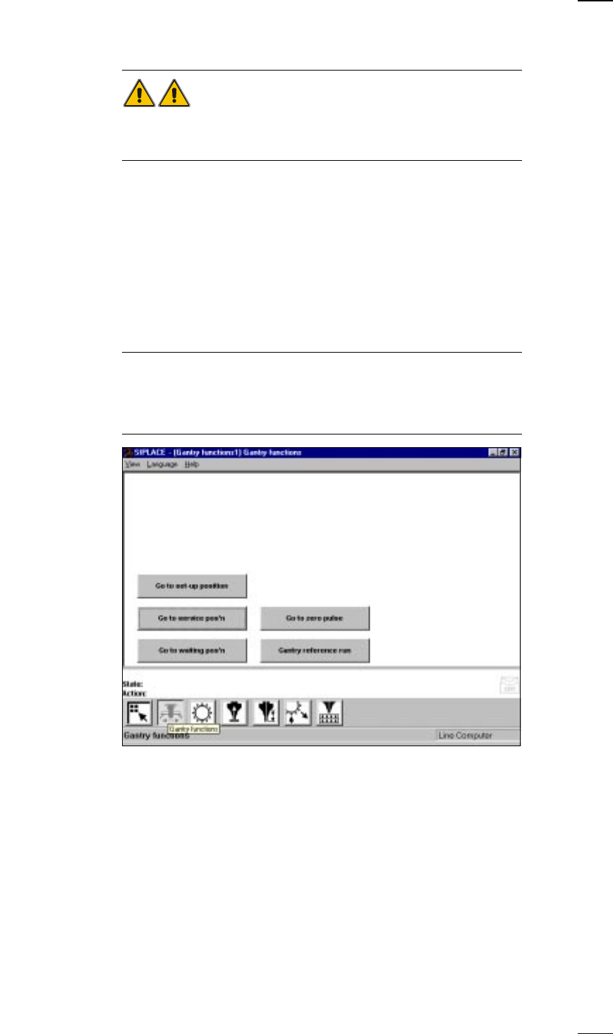
’Gantry functions’ menu
NOTE
All movement functions of the x and y gantry axes have to be initiated with
the Start button. You will be requested to do so by the on-screen display
’Press start key’.
If protective covers are still open, you will be asked to close them.
Go to set-up position Go to this position if you wish to refill or replace feeder modules.
Go to service pos’n Go to this position when you want to carry out servicing of the placement
head or gantry.
Go to waiting pos’n Move the gantry to this position if the gantry is not required.
Go to zero pulse The gantry travels until it reaches the zero pulse.
Gantry reference run The gantry carries out a reference run.
↑ UM 5.2.2
26
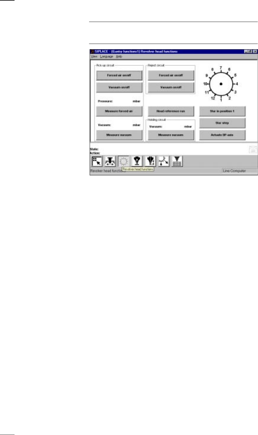
’Revolver head functions’ menu
NOTE
If you wish to carry out revolver head functions with the cover open, this
will only be possible with the key-operated switch in position "I".
Star in position 1 The star and the z axis of the revolver head carry out a reference run. At
the same time the segment at the star position is rotated into the pick-up /
placement position.
Star step The star is cycled onward by one position each time and its position dis-
played graphically in the window.
Actuate DP axis The nozzle of the segment at the dp1 turning station is rotated by 90°.
Head reference run The head axes carry out a reference run. During this, components are
ejected into the rejects container.
Pick-up circuit Forced air on/off The forced air is switched on or off
at the pick-up position.
Vacuum on/off The vacuum is switched on or off
at the pick-up position.
Measure forced air The pressure of the forced air is measured
at the pick-up position and the measured
value displayed in mbar.
Measure vacuum The vacuum value is measured for the
nozzle at the pick-up position and the
measured value displayed in mbar.
Reject circuit Forced air on/off The forced air is switched on or off
at the reject position.
Vacuum on/off The vacuum is switched on or off
at the reject position.
Holding circuit Measure vacuum The vacuum of the holding circuit is
measured and the measured value
displayed in mbar.
↑ UM 5.2.1