SOM-1747-003.pdf - 第22页
21 Tg0969-PM-SO 6.2 Cord Connection Diagrams 6.2 Cord Connection Diagrams Cord Connection Diagrams (Main Machine) Loads and Sensors in Each Block Input/Output Machine I/F Board Unit Assembly P .E.C. Recog- nition Camera …
20 Tg0969-PM-SO0311-002-(M801YRH-A1002)
Control Box
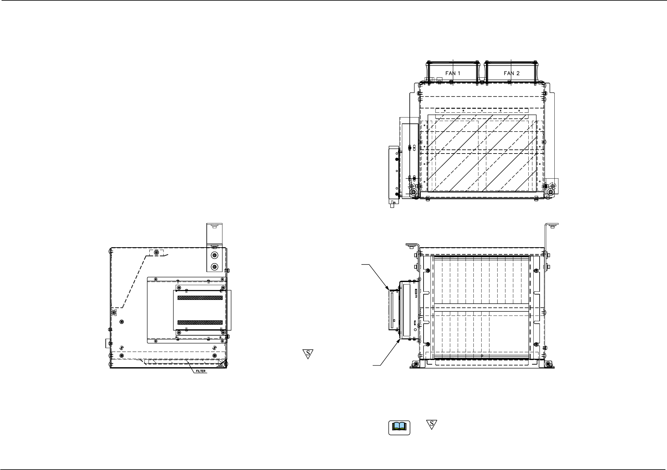
6.1 Parts Locations
Floppy Disk Drive (A-DRIVE)
CD-ROM Drive (E-DRIVE)
(a) -marked area is specially specified.
(b) CD-ROM Drive (E-DRIVE) is not installed in "C-S376-02".
Note
21 Tg0969-PM-SO
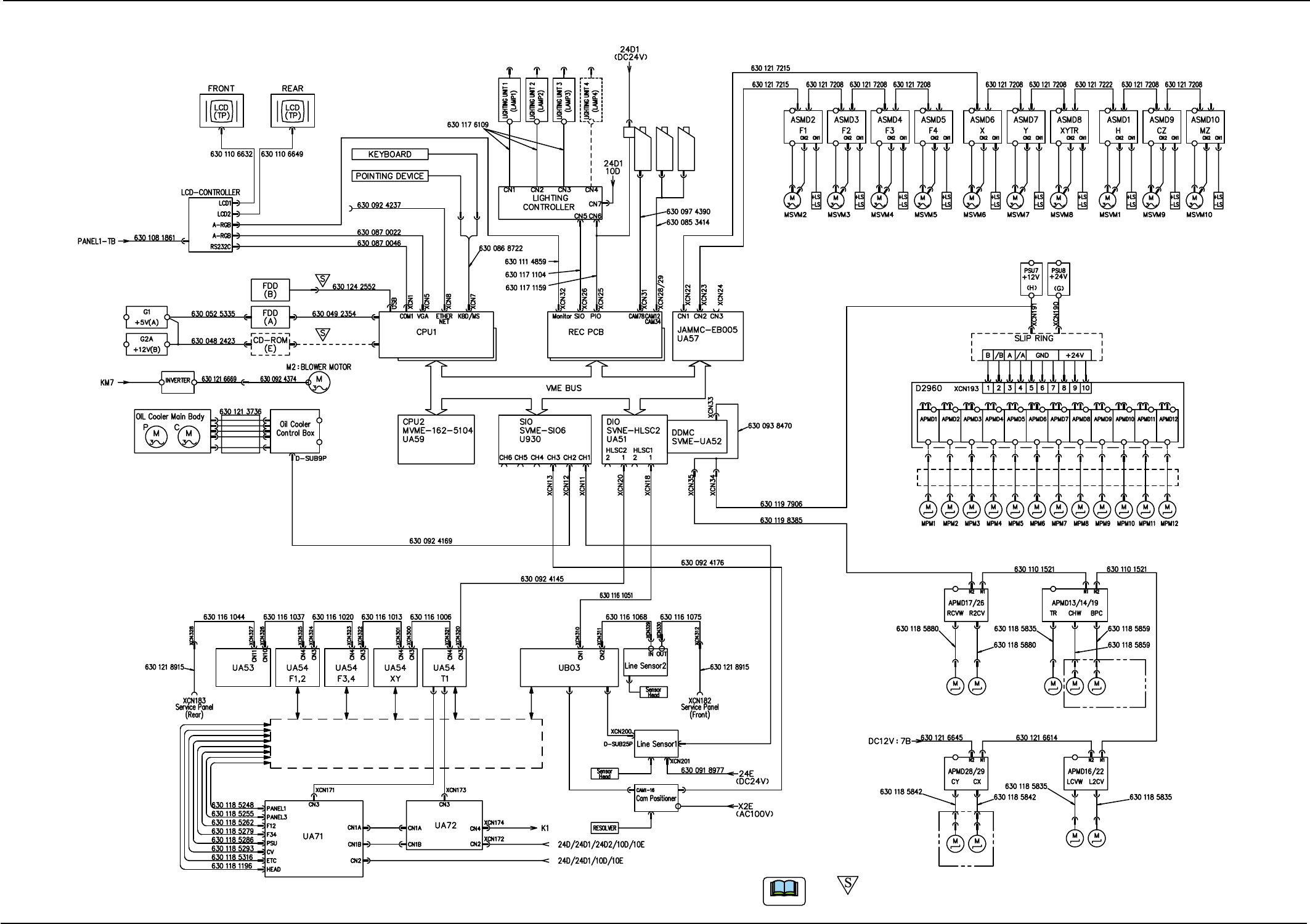
6.2 Cord Connection Diagrams
6.2 Cord Connection Diagrams
Cord Connection Diagrams (Main Machine)
Loads and Sensors
in Each Block
Input/Output
Machine I/F Board
Unit Assembly
P.E.C. Recog-
nition Camera
Camera for High
Magnification
Camera for Low
Magnification
0311-002-(M801JSB-A1010)
(a) -marked area is specially specified.
(b) CD-ROM Drive (E-DRIVE) is not installed in "C-S376-02".
Note
22 Tg0969-PM-SO
6.2 Cord Connection Diagrams
0311-002-(M801JSB-A1008)
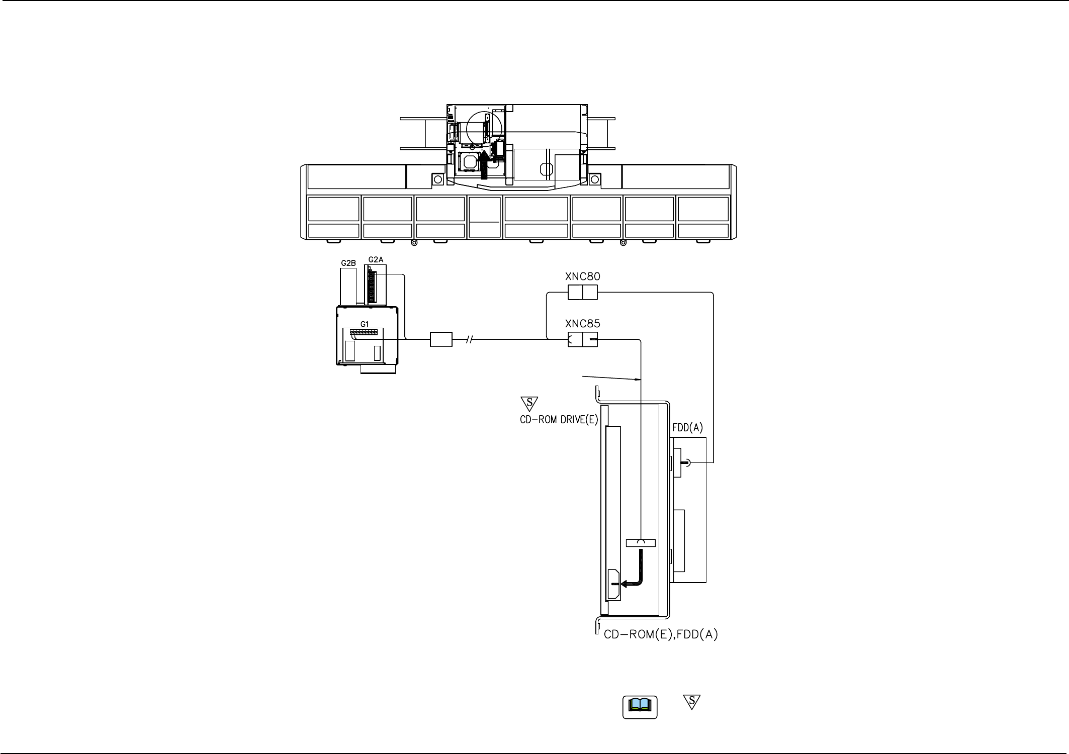
Connection Materials 2
630 048 2423
Control Box Section
Main Machine
Section1 DC Power
Supply Terminal
Control Box Section
Power Supply Unit
Connector for
CD-ROM
Power Supply
Connector for
FDD Power Supply
Rear View
(a) -marked area is specially specified.
(b) CD-ROM Drive (E-DRIVE) is not installed in "C-S376-02".
Note