SOM-1747-003.pdf - 第3页
Before Use • Identifying Alert Icons : This symbol mark represents danger or prompts warning. : This symbol mark represents prohibited operations. : This symbol mark represents forced operations or instructions. 2. Expla…
Before Use
We are grateful to you for purchasing these special specified
products.
Please keep in mind the following items before use.
1. Please read this instruction manual carefully for correct use of
these special specified products.
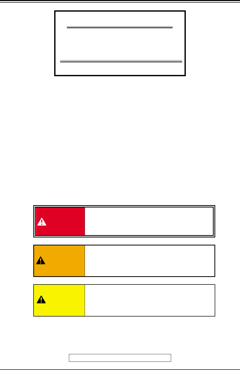
The following warning signs are classified into three catego-
ries according to the degree of danger.
Please fully understand the meaning of each sign for safety
precautions.
This indicates a potentially hazardous situation
which, if not avoided, may result in injury or physi-
cal damage.
CAUTION
DANGER
This indicates an imminently hazardous situation
which, if not avoided, will result in death or seri-
ous injury.
This indicates a potentially hazardous situation
which, if not avoided, could result in death or seri-
ous injury.
WARNING
This manual is made of recycled paper.
0404-003 1 Tg0969-PM-SO
SOM-1747-003
Installation of FDD/CD-ROM
C-S376-01,02
INSTRUCTION MANUAL
SPECIAL SPECIFICATIONS
TCM-X210 Series

Before Use
• Identifying Alert Icons
: This symbol mark represents danger or prompts
warning.
: This symbol mark represents prohibited operations.
: This symbol mark represents forced operations or
instructions.
2. Explained in this manual are only the items different from
those in the instruction manual of the main machine.
Use the instruction manual of the main machine together
with this manual.
3. The contents of this manual are subject to change without
prior notice.
Please contact our marketing department or sales ageny for
the detailed information on these special specifications.
0310-001 2 Tg0969-PM-SO

Contents
Page
0310-001 3 Tg0969-PM-SO
Before Use ................................................................................................... 1
Contents ....................................................................................................... 3
1. Scope ..................................................................................................... 4
2. Service Panel ......................................................................................... 5
3. Control Box ............................................................................................ 6
4. Description of Operation Windows ........................................................ 8
4.1 Save Operation of Recognized Image .............................................. 8
5. "FILE OPN." Window (Submenu)........................................................... 9
5.1 "Save / Load" Tab ............................................................................. 10
6. Materials ................................................................................................. 19
6.1 Parts Locations ................................................................................. 19
Service Panel .................................................................................... 19
Control Box ....................................................................................... 20
6.2 Cord Connection Diagrams .............................................................. 21
Cord Connection Diagrams (Main Machine)..................................... 21
Connection Materials 2 ..................................................................... 22