SIPLACE DX1DX2-Spec-设备性能参数-EN-DMS.pdf - 第15页
15 SIPLACE Placement Heads SIPLACE SpeedStar (C&P20) SIPLACE S peedS tar component camera type 23 (C&P20) Component range a a) Please note that the placeable comp onent range is also affected by the pad geometry,…
14
SIPLACE Placement Heads
Standard Functions / Options
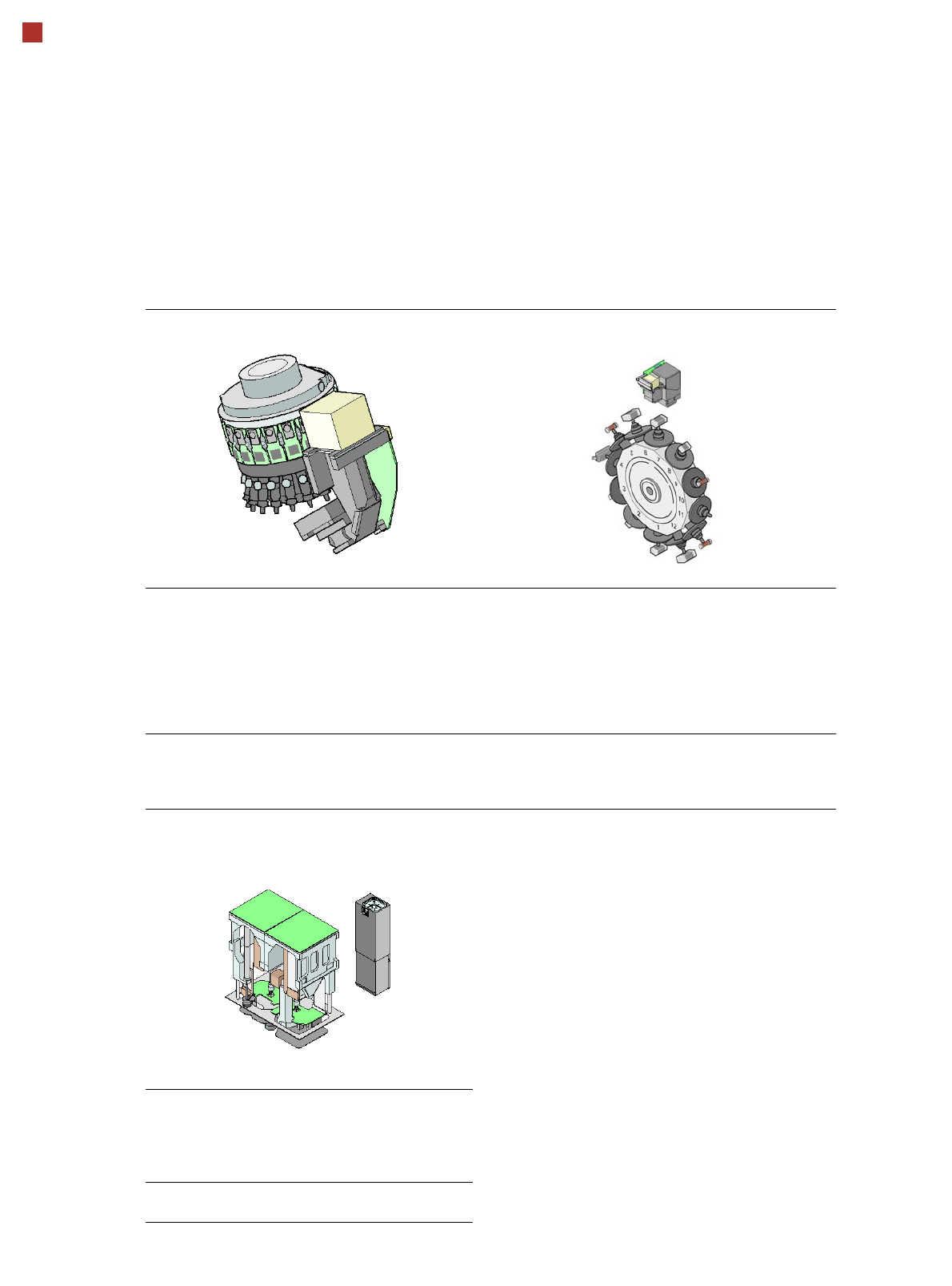
SIPLACE SpeedStar (C&P20) SIPLACE 12 segment Collect&Place head
(C&P12)
Standard-
functions
High-resolution camera, vacuum
sensor, force measurement,
component sensor, integrated
turning station per segment,
PCB warpage check, individual
image of each component
Standard-
functions
High-resolution camera,
vacuum sensor, force
measurement, compo-
nent sensor, integrated
turning station per seg-
ment, PCB warpage
check, individual image
of each component
Options Nozzle changer, special nozzles Options Nozzle changer, special
nozzles, high-resolution
head camera for 01005
components
SIPLACE TwinStar (TH)
Standard-
functions
Stationary fine pitch camera,
vacuum sensor, force measure-
ment, nozzle changer, PCB war-
page check, individual image of
each component
Options Stationary flip chip camera, spe-
cial nozzles, grippers
15
SIPLACE Placement Heads
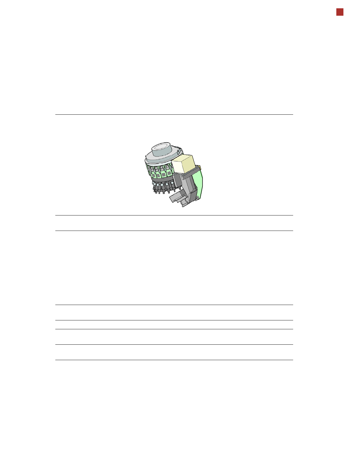
SIPLACE SpeedStar (C&P20)
SIPLACE SpeedStar
component camera type 23
(C&P20)
Component range
a
a) Please note that the placeable component range is also affected by the pad geometry, the customer-
specific standards, the component packaging tolerances and the component tolerances.
01005 to 2220, Melf,
SOT, SOD
Component spec.
max. height
min. lead pitch
min. lead width
min. ball pitch
min. ball diameter
min. dimensions
max. dimensions
max. weight
4 mm
0.25 mm
0.1 mm
0.4 mm
0.2 mm
0.4 mm x 0.2 mm
6 mm x 6 mm
1 g
Programmable set-down
force
1.5 N - 4.5 N
Nozzle types 10xx, 11xx, 12xx
X/Y accuracy
b
b) Accuracy values measured in accordance with vendor-neutral IPC standard.
± 41 µm/3
± 55 µm/4
Angular accuracy ± 0.5° / 3
± 0.7° / 4
16
SIPLACE Placement Heads
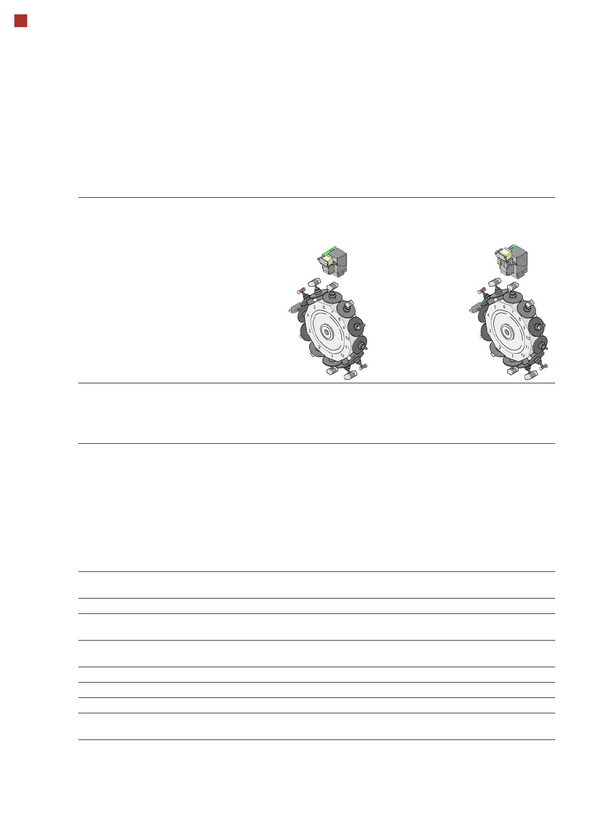
SIPLACE 12 segment Collect&Place (C&P12)
12 segment
Collect&Place head
component camera
28
12 segment
Collect&Place head
component camera
30
Component range
a
a) Please note that the placeable component range is also affected by the pad geometry, the customer-specific standards,
the component packaging tolerances and the component tolerances.
0402 to PLCC44,
BGA, µBGA, Flip-
Chip, TSOP, QFP,
SO to SO32, DRAM
0201
b
to Flip-Chip,
Bare Die, PLCC44,
BGA, µBGA, TSOP,
QFP, SO to SO32,
DRAM
b) with 0201 package
Component spec.
max. height
min. lead pitch
min. lead width
min. ball pitch
min. ball diameter
min. dimensions
max. dimensions
max. weight
6 mm
0.5 mm
0.2 mm
0.35 mm
0.2 mm
1.0 x 0.5 mm²
18.7 x 18.7 mm²
2 g
6 mm
0.3 mm
0.15 mm
0.25 mm
0.14 mm
0.6 x 0.3 mm²
18.7 x 18.7 mm²
2 g
Programmable set-down
force
2.4 N - 5.0 N 2.4 N - 5.0 N
Nozzle types 3xx 3xx
X/Y accuracy
c
c) The accuracy value was measured using the vendor-neutral IPC standard.
± 45 µm/3
± 60 µm/4
± 41 µm/3
± 55 µm/4
Angular accuracy ± 0.5° / 3
± 0.7° / 4
± 0.5° / 3
± 0.7° / 4
Component spectrum 98% 98.5%
Component camera type 28 30
Illumination levels 5 5
Possible illumination
level settings-
256
5
256
5