SIPLACE DX1DX2-Spec-设备性能参数-EN-DMS.pdf - 第17页
17 SIPLACE Placement Heads SIPLACE TwinStar (TH) SIPLACE T winSt ar Fine-pitch camera (com- ponent camera type 36 ) SIPLACE T winSt ar Fine-pitch camera (com- ponent camera type 33 ) SIPLACE TwinStar Flip-Chip camera (co…
16
SIPLACE Placement Heads
SIPLACE 12 segment Collect&Place (C&P12)
12 segment
Collect&Place head
component camera
28
12 segment
Collect&Place head
component camera
30
Component range
a
a) Please note that the placeable component range is also affected by the pad geometry, the customer-specific standards,
the component packaging tolerances and the component tolerances.
0402 to PLCC44,
BGA, µBGA, Flip-
Chip, TSOP, QFP,
SO to SO32, DRAM
0201
b
to Flip-Chip,
Bare Die, PLCC44,
BGA, µBGA, TSOP,
QFP, SO to SO32,
DRAM
b) with 0201 package
Component spec.
max. height
min. lead pitch
min. lead width
min. ball pitch
min. ball diameter
min. dimensions
max. dimensions
max. weight
6 mm
0.5 mm
0.2 mm
0.35 mm
0.2 mm
1.0 x 0.5 mm²
18.7 x 18.7 mm²
2 g
6 mm
0.3 mm
0.15 mm
0.25 mm
0.14 mm
0.6 x 0.3 mm²
18.7 x 18.7 mm²
2 g
Programmable set-down
force
2.4 N - 5.0 N 2.4 N - 5.0 N
Nozzle types 3xx 3xx
X/Y accuracy
c
c) The accuracy value was measured using the vendor-neutral IPC standard.
± 45 µm/3
± 60 µm/4
± 41 µm/3
± 55 µm/4
Angular accuracy ± 0.5° / 3
± 0.7° / 4
± 0.5° / 3
± 0.7° / 4
Component spectrum 98% 98.5%
Component camera type 28 30
Illumination levels 5 5
Possible illumination
level settings-
256
5
256
5
17
SIPLACE Placement Heads
SIPLACE TwinStar (TH)
SIPLACE TwinStar
Fine-pitch camera (com-
ponent camera type 36)
SIPLACE TwinStar
Fine-pitch camera (com-
ponent camera type 33)
SIPLACE TwinStar
Flip-Chip camera (compo-
nent camera type 25)
Component range
a
a) Please note that the placeable component range is also affected by the pad geometry, the customer-specific standards,
the component packaging tolerances and the component tolerances.
0603 to SO, PLCC, QFP,
BGA, special compo-
nents, bare dies, flip-
chips
0402 to SO, PLCC, QFP,
BGA, special compo-
nents, bare dies, flip-
chips
0201 to SO, PLCC, QFP,
sockets, plugs, BGA, spe-
cial components, bare
dies, flip-chips, shields
Component specs
b
b) If the MultiStar and TwinStar are combined in the same placement area, the maximum component height may be restrict-
ed.
max. height 25 mm 25 mm 25 mm
min. lead pitch 0.4 mm 0.3 mm 0.25 mm
min. lead width 0.24 mm 0.15 mm 0.1 mm
min. ball pitch 0.56 mm 0.35 mm 0.14 mm
min. ball diameter 0.32 mm 0.2 mm 0.08 mm
min. dimensions 1.6 mm x 0.8 mm 1.0 mm x 0.5 mm 0.6 mm x 0.3 mm
max. dimensions
Single measurement 32 mm x 32 mm 55 mm x 45 mm 16 mm x 16 mm
Multiple measurement -- -- 55 mm x 55 mm
For use with two nozzles: 50 mm x 50 mm or
69 mm x 10 mm
--
For use with one nozzle: 78 mm x 78 mm or
110 mm x 10 mm
up to 200 mm x 110 mm
(with restrictions)
--
max. weight
c
c) If standard nozzles are used.
100 g 100 g 100 g
Programmable set-down
force
1.0 N - 15 N
2.0 N - 30 N
d
1.0 N - 15 N
2.0 N - 30 N
d
d) SIPLACE High-Force Head.
1.0 N - 15 N
2.0 N - 30 N
d
Nozzle types
e
e) Over 300 different nozzles and 100 gripper types are available, with an extensive nozzle database available online.
5xx (standard)
4xx + adapter
8xx + adapter
9xx + adapter
gripper
5xx (standard)
4xx + adapter
8xx + adapter
9xx + adapter
gripper
5xx (standard)
4xx + adapter
8xx + adapter
9xx + adapter
gripper
Nozzle spacing for P&P
heads
70.8 mm 70.8 mm 70.8 mm
X/Y accuracy
f
± 36 µm/3± 50 µm/4 ± 26 µm/3± 35 µm/4 ± 22 µm/3± 30 µm/4
Angular accuracy ± 0.05° / 3± 0.07°/ 4 ± 0.05° / 3± 0.07°/ 4 ± 0.05° / 3± 0.07° / 4
Illumination levels 6 6 6
Possible illumination level
settings
256
6
256
6
256
6
f) Accuracy values measured in accordance with vendor-neutral IPC standard.
18
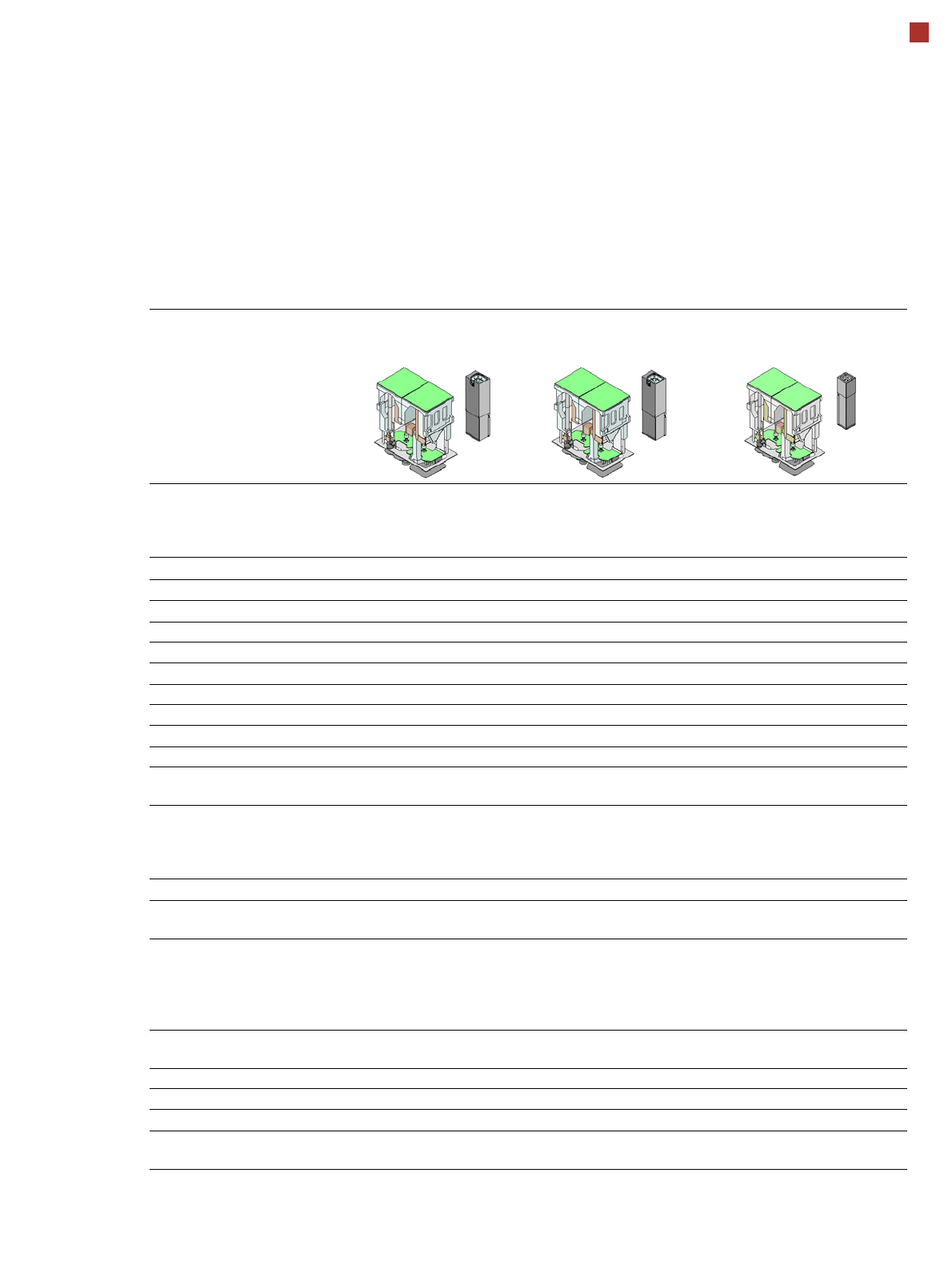
SIPLACE Placement Heads
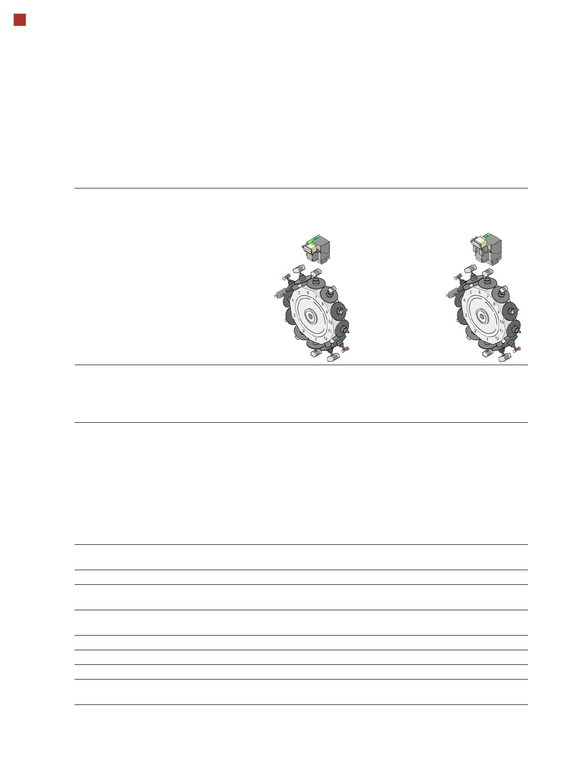
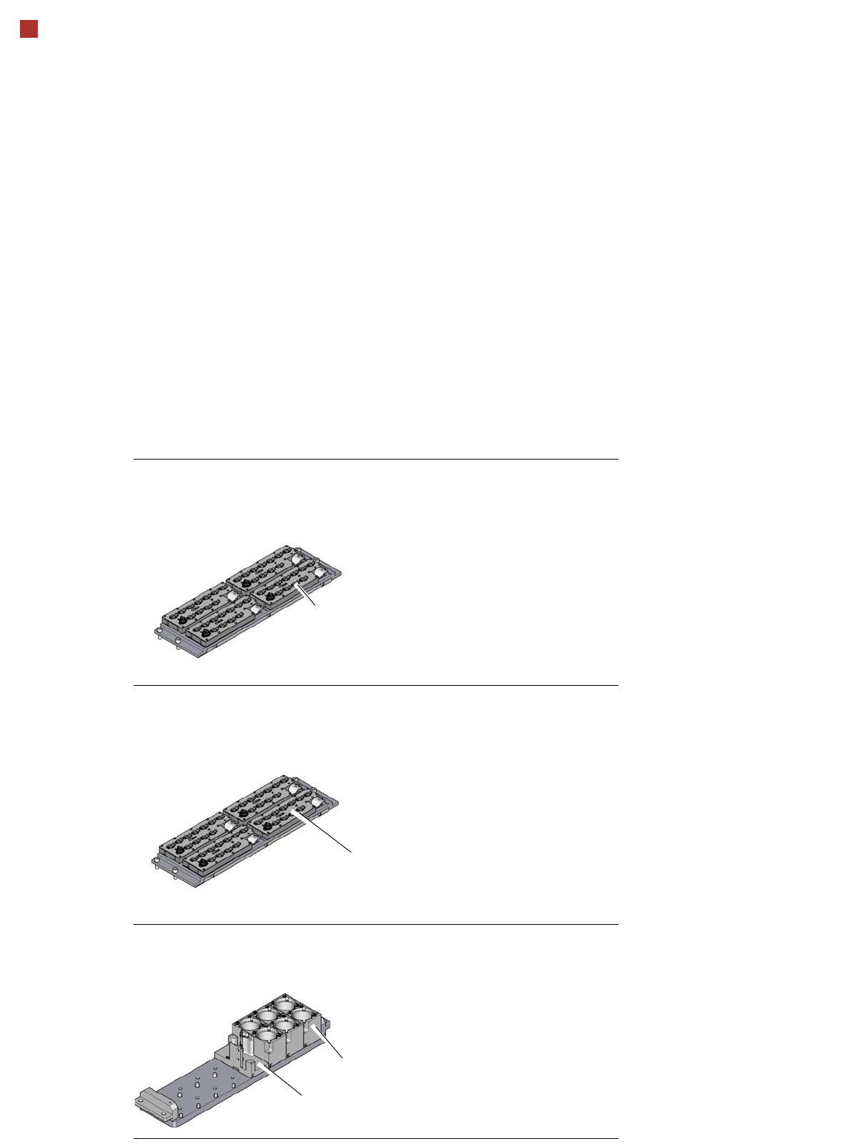
Nozzle Changers
Nozzle changer for the SIPLACE SpeedStar
Nozzle changer for the 12 segment Collect&Place
Nozzle changer for the SIPLACE TwinStar
Magazine for 12
type 10xx, 11xx or 12xx nozzles
Magazines for 12
nozzles of type 3xx
Magazine for two standard nozzles
Magazine for one special nozzle, gripper
Description
Nozzle changers increase the flexibility of the placement heads when it comes to processing
different components. The nozzle configuration can be rapidly adjusted to changing place-
ment jobs. Precisely defined positions and perfect nozzle seat in the garage ensure minimum
radial eccentricity on the placement head.
The nozzle changers are equipped with inbuilt monitors which check whether the nozzle mag-
azine is seated correctly on the mount. In addition, the nozzle changers recognize whether
the magazines are for 10xx, 20xx or 28xx nozzles by the code.