Printer 600 Machine PC.pdf - 第16页
0$&+,1( 3& 9,6,213&$ '$3725& $5' 5.16 Technical Reference Manual Chapter Issue 3 May 03 Card - Pt No 155543 The V ision PC Adaptor Card i s located in sl ot PCI 1 of the enclosur e. The card…
0$&+,1(3&
9,6,213&$'$3725&$5'
Chapter Issue 3 May 03 Technical Reference Manual 5.15
VISION PC ADAPTOR CARD
There are two versions of Vision PC Adaptor card available within the PC
enclosure. Each type of card is described below.
Card - Pt No
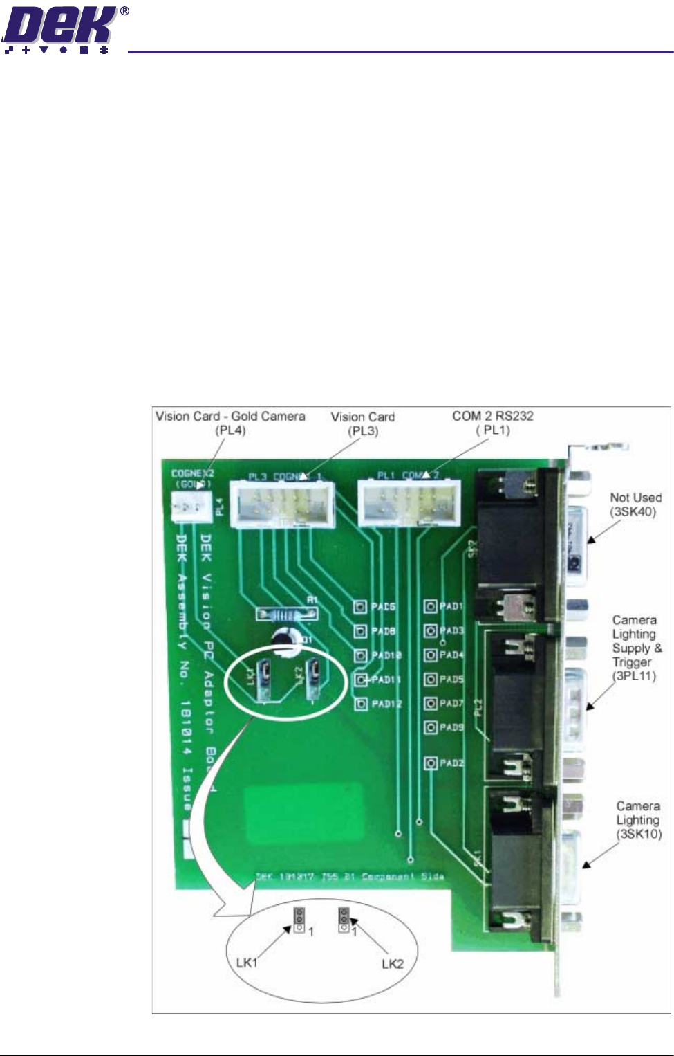
181014
The Vision PC Adaptor Card is located in slot ISA 5 of the enclosure. The card
routes signals from the SBC Processor and the Vision Processor Cards to
control the camera lighting at the camera.
An on-board FET device (Q1) inverts the strobe signal from the vision processor
to condition the signal for compatibility with the control board input for the
camera lighting. 3PL11 feeds power on to the camera control board via links to
3SK10.
3SK10 is an RS232 Serial Communications link. Communications are estab-
lished between the vision processor and the camera control board. A serial
data stream is fed back from the control board to confirm that the correct camera
is being used and the set up data (if LED’s are switched on) is routed to the
camera lighting boards on the camera assembly.
Figure 5-7 Vision Adaptor Card Layout - Pt No 181014
0$&+,1(3&
9,6,213&$'$3725&$5'
5.16 Technical Reference Manual Chapter Issue 3 May 03
Card - Pt No
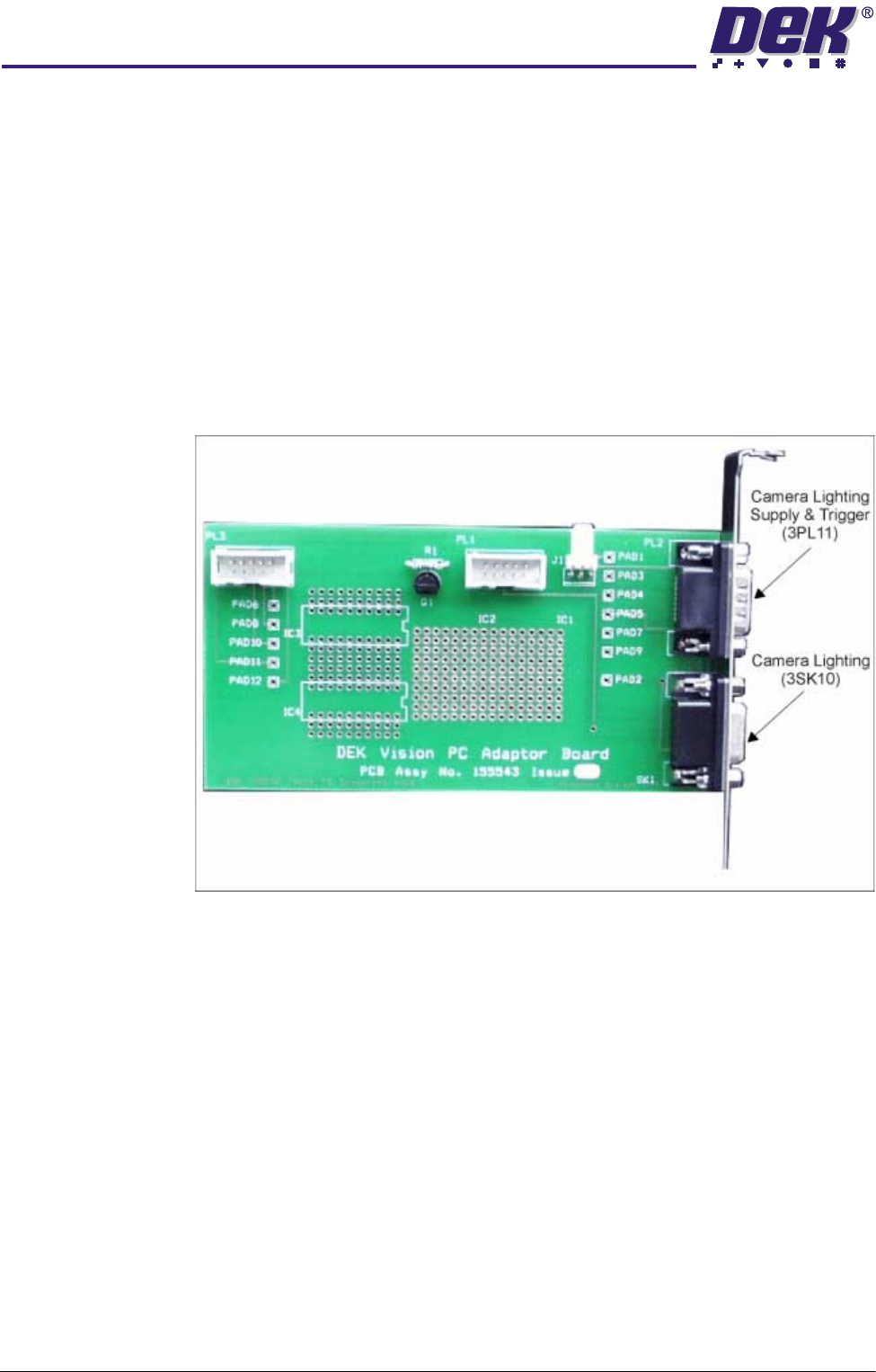
155543
The Vision PC Adaptor Card is located in slot PCI 1 of the enclosure. The card
routes signals from the SBC Processor and the Vision Processor Card to control
the camera lighting at the camera.
An on-board FET device (Q1) inverts the strobe signal from the vision processor
to condition the signal for compatibility with the control board input for camera
lighting. 3PL11 feeds power on to the upper and lower lighting boards via links
to 3SK10.
3SK10 is an RS232 Serial Communications link. Communications are estab-
lished between the vision processor and the camera control board. A serial
data stream is fed back from the control board to confirm that the correct camera
is being used and the set up data (if LED’s are switched on) is routed to the
camera lighting boards on the camera assembly.
Figure 5-8 Vision Adaptor Card Layout - Pt No 155543
0$&+,1(3&
3&,%
Chapter Issue 3 May 03 Technical Reference Manual 5.17
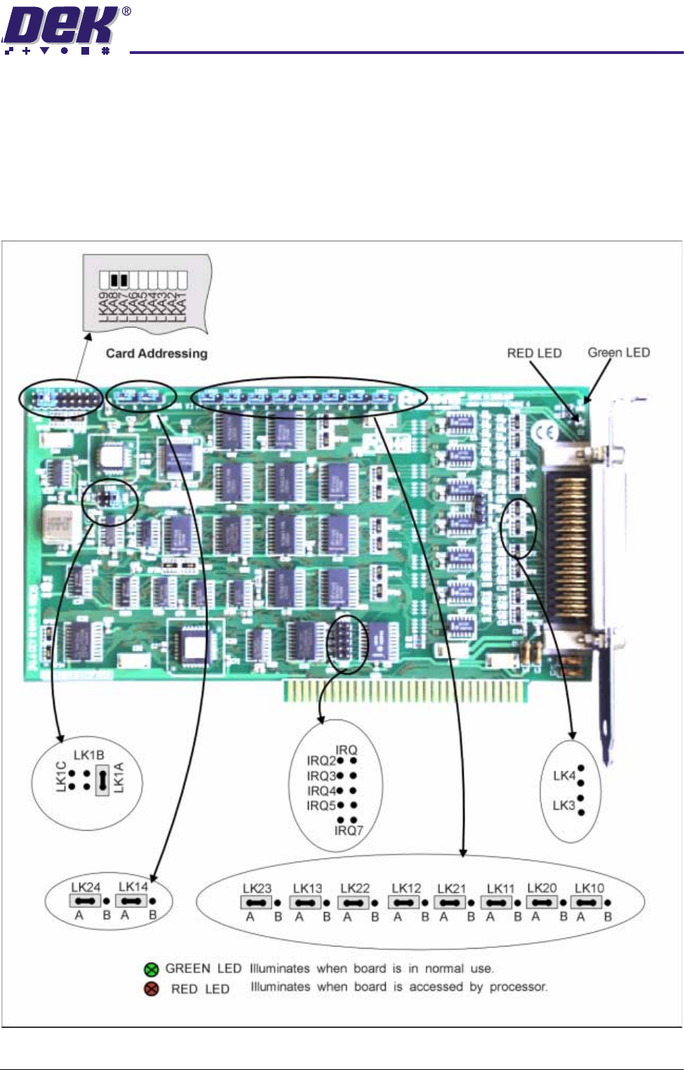
PCIB 40 The PCIB40 card is fitted to card slot position ISA 9 if the AutoFlex tooling
option is fitted to the machine. PCIB40 is a 40 channel I/O board, divided into
five sub groups of 8 bits. The card provides addressing signals to the five cards
(X1-X5) within the Y15 enclosure. These cards in-turn drive the electromag-
netic coils which hold the tooling pins in place. The power and clamp output
signals are utilized to enable power to the coils and to signal to the driver cards
the extent of power used eg, power on/off and power low/high respectively
Figure 5-9 PCIB 40 Card Layout