Printer 600 Machine PC.pdf - 第20页
0$&+,1( 3& 5($53$1 (/&211(& 725)81&7 ,216 5.20 Technical Reference Manual Chapter Issue 3 May 03 REAR P ANEL CONNECTOR FUNCTIONS ISA 9 (AutoFlex T ooling Option) 3SK16 PCIB40 Autoflex ISA 7 (Not F…
0$&+,1(3&
&+$11(/56&2006&$5'
Chapter Issue 3 May 03 Technical Reference Manual 5.19
4 CHANNEL RS232 COMMS CARD
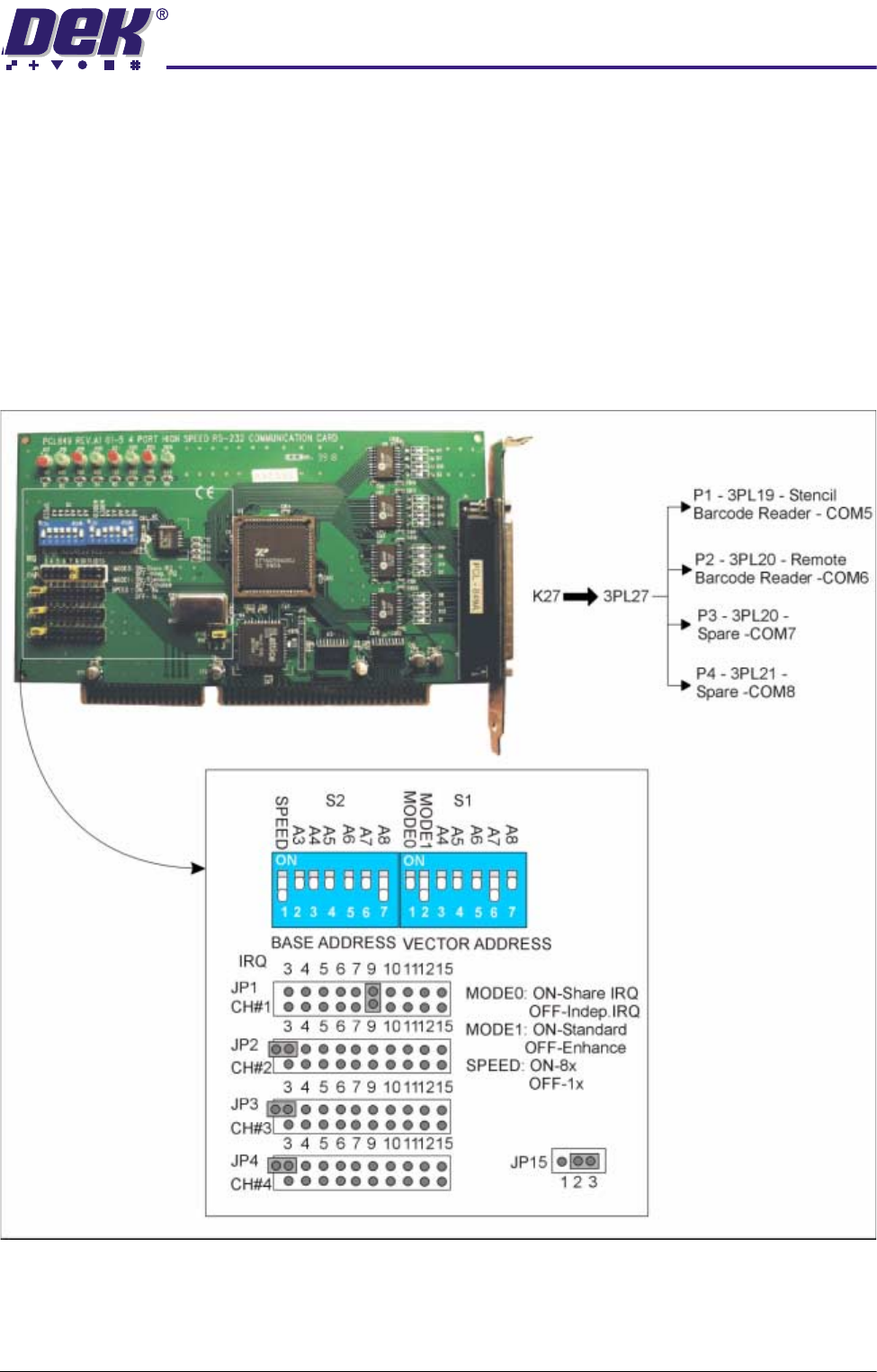
The RS232 4 channel communications card, fitted to slot ISA 7, is used to
interface with external communication devices such as the stencil barcode
reader (COM5) and the remote barcode reader (COM6). This card uses a
shared interrupt (IRQ) level for the available options. The output socket 3SK27
is broken out into individual comms channels via a four by nine way ‘D’ plug
octopus cable. The cable and output channel identification, DIP switch and
jumper link settings are shown below.
NOTE
This card is not fitted to all machines.
Figure 5-10 4 Channel RS232 Comms Card
0$&+,1(3&
5($53$1(/&211(&725)81&7,216
5.20 Technical Reference Manual Chapter Issue 3 May 03
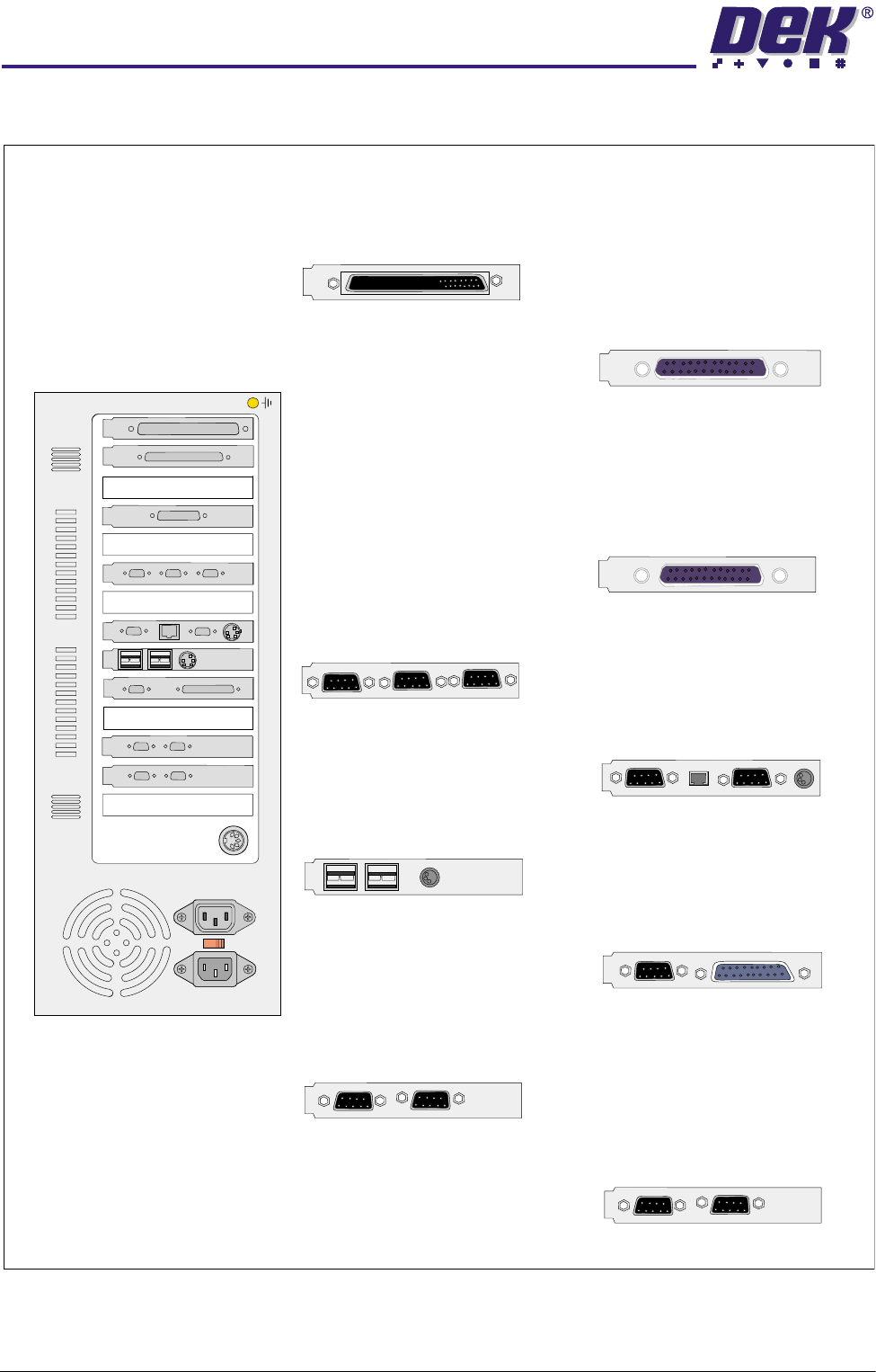
REAR PANEL CONNECTOR FUNCTIONS
ISA 9
(AutoFlex Tooling Option)
3SK16
PCIB40
Autoflex
ISA 7
(Not Fitted In All Machines)
3SK27
Stencil
Barcode
COM5
(Option)
Remote
Barcode
COM6
(Option)
COM7 &
COM8
Spare
3SK04
Keyboard
3SK05
SVGA
3SK02
LAN
3PL03
Touchscreen
COM1
ISA 3
3SK06
Printer
3PL39
Not Used
ISA 1
3SK08
Camera 0
3SK09
Not Used
PCI 3
3SK12
NextMove
ISA 10
3SK10
Camera Lighting
COM 2
3SK40
Not Used
3PL11
Camera Lighting
Supply & Trigger
ISA 5
3SK30
Camera 0
3SK31
Not Used
PCI 2
(Gold Camera Option)
3SK07
Mouse
ISA 2
3SK37, 36
Not Used
3SK35, 34
Not Used
PC Enclosure
Rear Panel
230V
ISA 2
ISA 1
PCI 1
ISA 3
ISA 4
ISA 5
ISA 6
ISA 7
ISA 8
ISA 9
ISA 10
PCI 2
PCI 4
PCI 3
0$&+,1(3&
5($53$1(/&211(&725)81&7,216
Chapter Issue 3 May 03 Technical Reference Manual 5.21
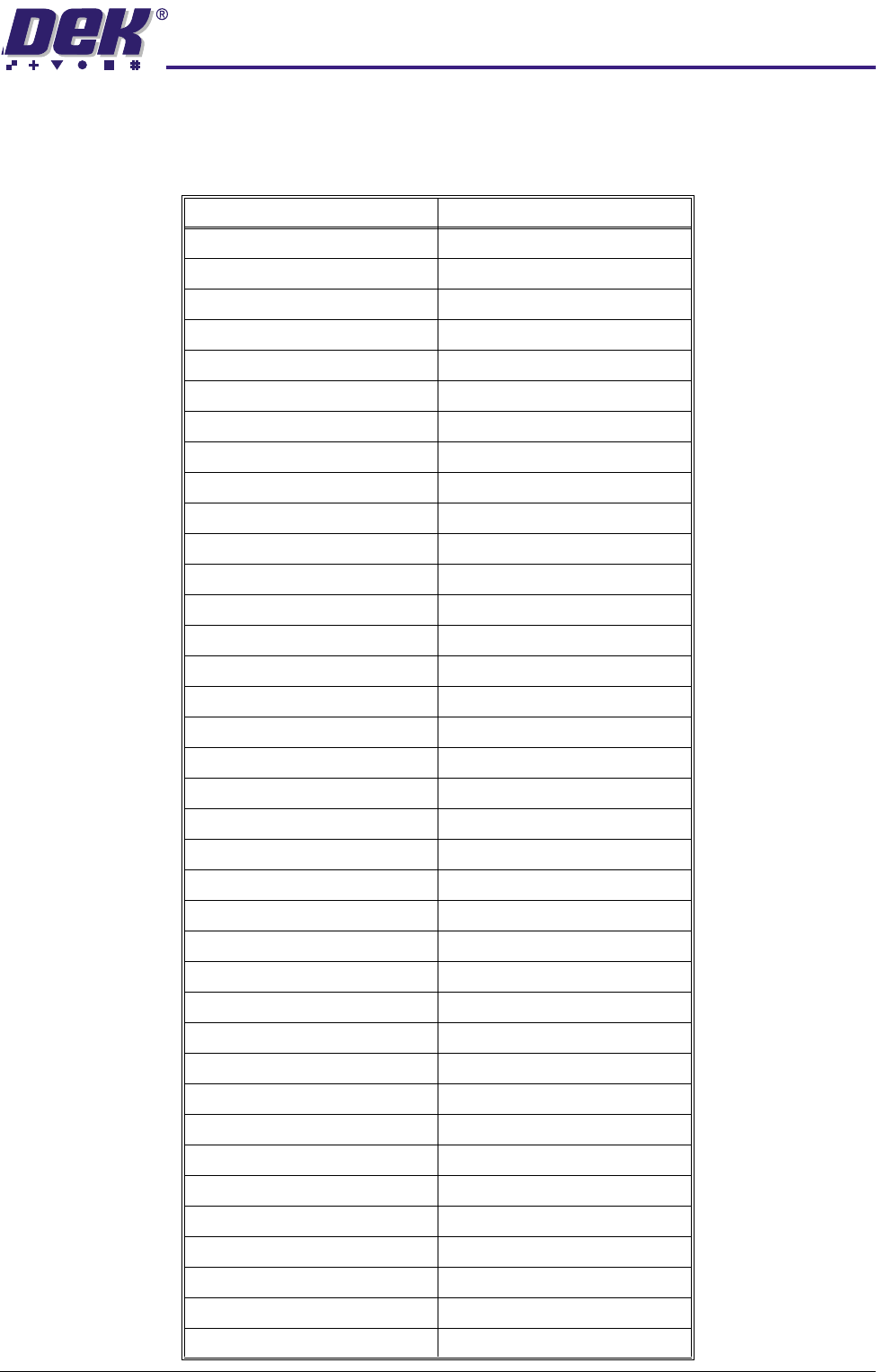
NextMove ISA 10
3SK12 Yamaichi 100 Way Connector
Connector 3SK12 Left Row Connector 3SK12 Right Row
PIN 1 ANALOG GND PIN 1 ADC2
PIN 2 ADC1 PIN 2 ADC0
PIN 3 ADC3 PIN 3 ADC6
PIN 4 ADC5 PIN 4 ADC4
PIN 5 ADC7 PIN 5 DAC2
PIN 6 DAC1 PIN 6 DAC0
PIN 7 DAC3 PIN 7 DOP1
PIN 8 DOP0 PIN 8 ANALOG GND
PIN 9 DOP2 PIN 9 DOP5
PIN10 DOP4 PIN10DOP3
PIN 11 DOP6 PIN 11 DOP9
PIN 12 DOP8 PIN 12 DOP7
PIN 13 DOP10 PIN 13 USR GND
PIN 14 USER V+ PIN 14 DOP11
PIN 15 CAN WIRE+ PIN 15 ENCO.1
PIN 16 !EXT.INT.U PIN 16 CAN WIRE-
PIN 17 ENCO!! PIN 17 ENCO.A
PIN 18 ENCO!B PIN 18 ENCO.B
PIN19 ENCO!A PIN 19 ENC1.B
PIN 20 ENC1!! PIN 20 ENC1.1
PIN 21 ENC1 !B PIN 21 ENC2.1
PIN 22 ENC1 !A PIN 22 ENC1.A
PIN 23 ENC2!! PIN 23 ENC2.A
PIN 24 ENC2 !B PIN 24 ENC2.B
PIN 25 ENC2 !A PIN 25 ENC3.B
PIN 26 ENC3!! PIN 26 ENC3.1
PIN 27 ENC3 !B PIN 27 USR V+
PIN 28 ENC3 !A PIN 28 ENC3.A
PIN 29 PULSE 0 PIN 29 PULSE 1
PIN 30 BOOST 0 PIN 30 DIR 0
PIN 31 DIR1 PIN 31 DIR 2
PIN 32 PULSE 2 PIN 32 BOOST 0
PIN 33 BOOST 2 PIN BOOST 3
PIN 34 DIR 3 PIN 34 PULSE 3
PIN 35 USER GND PIN 35 DIG.IN.2
PIN 36 DIG.IN.1 PIN 36 DIG.IN.0
PIN 37 DIG.IN.3 PIN 37 DIG.IN.6