IPC-4552.pdf - 第17页
IPC-4552 Proposal June 2001 and calibration files for ENIG measurements to using an x -ray tube that is too high in energ y that blasts its way through the gold layer. In an attempt to overco me some of these issues and …
IPC-4552 Proposal June 2001
1
2
3
4
5
6
7
8
9
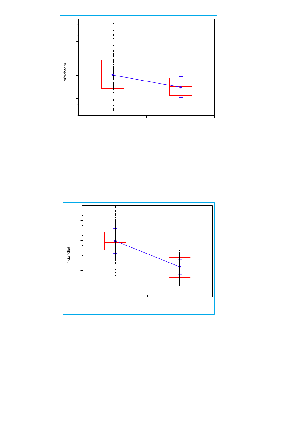
vendor D vendor E
vendor
Means and Std Deviations
Level Number Mean Std Dev Std Err Mean
vendor D 300 4.07967 1.59078 0.09184
vendor E 300 2.99307 0.95200 0.05496
Fig 5: Comparison of gold plating thickness variation by vendor for similar bath life conditions
110
120
130
140
150
160
170
180
190
vendor D vendor E
vendor
Means and Std Deviations
Level Number Mean Std Dev Std Err Mean
vendor D 300 159.624 12.9179 0.74581
vendor E 300 133.816 7.6477 0.44154
Fig 6: Comparison of nickel plating thickness variation by vendor for similar bath life conditions
Page 14 of 10
Download From http://bbs.infoeach.com
Download From http://bbs.infoeach.com

IPC-4552 Proposal June 2001
and calibration files for ENIG measurements to using an x-ray tube that is too high in energy that blasts its
way through the gold layer.
In an attempt to overcome some of these issues and to gain an understanding of the correct way to measure ENIG,
the committee enlisted the aid of Veeco, one of the industry suppliers of XRF equipment. Veeco has at its
headquarters a very expensive XRF unit, costing in excess of $500,000 that would be used as the de-facto
measurement tool. As a comparison to this reference unit would be a modern, thin film measurement capable XRF
unit typically found in a PWB shop or at incoming inspection at the OEM, price range of $50,000.
For the XRF measurement test, thirty measurements would be taken at predetermined pad locations per panel,
(fifteen on each side of the board). The data generated by each XRF machine would be compared to determine if
they were statistically the same. Refer to Figure 3.
The results from the studies were as follows:
1) There is a difference between chemical suppliers of ENIG as regard deposit thickness rates and
maximum thickness achievable under the conditions of this test.
2) The requirements of some OEM’s / EMS’s for 10 microinches of gold cannot be met under the
conditions of the test.
3) The range of nickel deposited would fall on average between 100 and 200 microinches.
4) The capability of a “working mans” XRF as compared to a state of the art XRF for ENIG measurement
is good with their being a very small statistical difference in the values recorded.
Minimum Gold Thickness Requirements:
Once the thickness of the deposits were verified the most important question could begin to be answered. While the
deposit is multifunctional in nature, something that is covered in the specification, the primary use is one of
soldering and as solderability preservative. What would be the minimum thickness of gold needed to afford shelf life
for upwards of one year? As mentioned above, the plating rate study was performed on wetting balance coupon
panels.
Solderability Testing:
The solderability testing would be carried out on a wetting balance using a test flux complying with ROL0 of the J-
Std-004 specification – i.e. a test flux. For each test, ten (10) samples would be tested and the average value of these
ten (10) readings would be reported. Therefore ten (10) tests were performed on the two- (2) minute plating time
group, ten (10) on the 4 minute plating group etc. A total of 100 soldering tests per vendor tested would be
performed for the “as received” condition. It was decided that it would not be practical to test all five suppliers given
the time constraints that the committee was working to, so as a compromise two vendors were chosen at random
from the groups: Vendor D and Vendor E. Fig 5 & 6, show thickness distribution. Figs 7 & 8 show wetting balance
as a function of dwell time in the gold bath.
The test protocol was as follows:
Each panel contains 27 strips of test coupons with 14 coupons per strip.
The coupons were scored and routed to enable them to be tested more easily and consistently.
The coupon is 25.4 mm wide, 1.6 mm thick and has a wettable area of 36 mm that is made up from twelve (12) 3mm
wide pads and is made from acid copper plated FR4 material Fig 4.
Each coupon is dipped into the test flux for five (5) seconds and excess flux is removed by touching the sample to a
piece of lab paper
The sample is allowed to dry completely prior to placing into the specimen holder of the wetting balance.
An automatic dross skimmer cleans the solder pot surface as the test begins.
The sample is dipped at 90° degrees incident to the solder with no preheat.
The depth of immersion is 0.5mm and the dip time is 10 seconds.
The wetting balance used has the ability to discriminate between the wetting forces produced by the sample (which
are small) compared to the forces that are produced by the buoyancy of the coupon which are large.
Page 15 of 10
Download From http://bbs.infoeach.com
Download From http://bbs.infoeach.com
IPC-4552 Proposal
-0.05
0.00
0.05
0.10
0.15
0.20
0.25
0
0.375
0.75
1.125
1.5
1.875
2.25
2.625
3
3.375
3.75
4.125
4.5
4.875
5.25
5.625
6
6.375
6.75
7.125
7.5
7.875
8.25
8.625
9
9.375
9.75
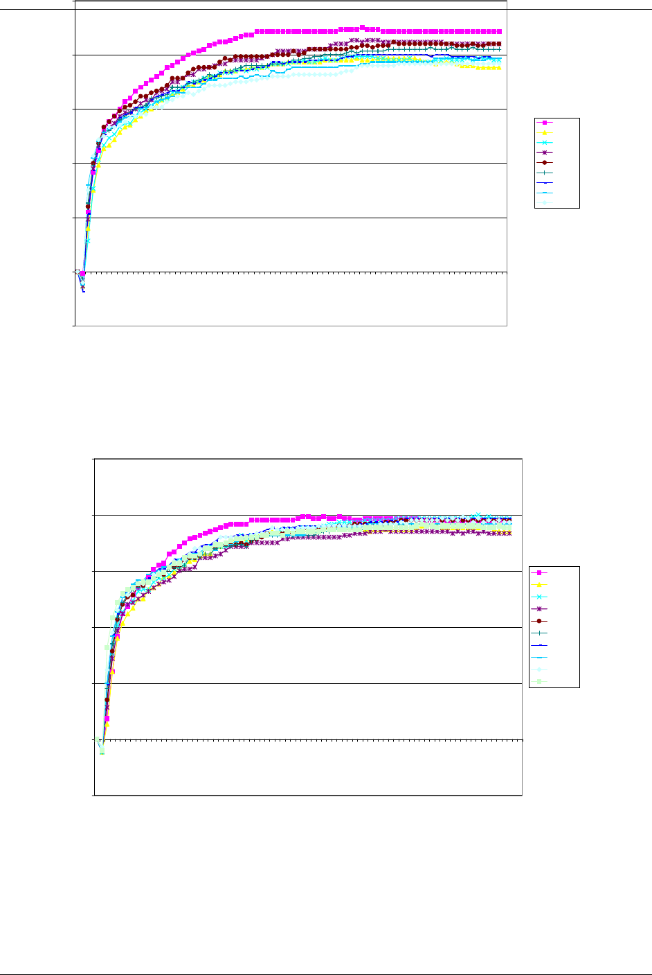
time in seconds
mN/mm
2 mins
4 mins
6 mins
8 mins
10 mins
12 mins
14 mins
16 mins
18 mins
June 2001
Page 16 of 10
Fig 7: Wetting times as a function of plating dwell times for Vendor E, 90 days old
-0.05
0.00
0.05
0.10
0.15
0.20
0.25
0
0.375
0.75
1.125
1.5
1.875
2.25
2.625
3
3.375
3.75
4.125
4.5
4.875
5.25
5.625
6
6.375
6.75
7.125
7.5
7.875
8.25
8.625
9
9.375
9.75
time in seconds
mN/mm
2mins
4 mins
6 mins
8 mins
10 mins
12 mins
14 mins
16 mins
18 mins
20 mins
Fig 8: Wetting times as a function of plating dwell times for Vendor D, 90 days old
Download From http://bbs.infoeach.com
Download From http://bbs.infoeach.com