EIA-481-D中文版----美国电子工业协会.pdf - 第11页
EIA-481-D Page 5 Left Intentionally Blank 本页空白
EIA-481-D
Page
4
准的刻度值)。拔离是指从载体分离全部宽度的覆盖带或从载体上剥离覆盖带的中心部分,使得元件可以从格子中取出。拉力的
方向应与载体运行方向相反,并且拉伸的覆盖带与载体顶部呈165~180的夹度。在撕力测试中,覆盖带应以相对于载体300+/-10
毫米/分的速度拉伸,这将使得覆盖带/载体的封合以150毫米/分钟的速率分离。
4.12 Bar code labeling (if required) shall be on the side of the reel opposite the round sprocket holes (refer to
4.2(c) and Figure 10). Refer to EIA-556 and EIA-624.
条形码(如需要)应贴在圆形齿孔对面的卷轴侧(参照4.2(c) 和图10),参照EIA-556和EIA-624。
4.13 Reels as defined by Figure 14 shall be permanently marked with visible recycling symbology.
如图示14 详细说明,卷轴应该有明显且永久的回收标志。
4.14 The following orientation rules shall be considered as standard for multi-connection components.
对于多引脚元件的摆放方向必须遵循下列的标准:
(a) Traditionally packaged components with leaded, bottom-only terminations (e.g. PLCC, SOIC,
SOJ,
and BGA) shall be packaged with the terminations facing the bottom of the carrier cavity. The
following rules apply whether the terminations are facing downward or upward in the cavity.
传统封装,只有底面上有上锡引脚接线端的元件(如:带引线的塑料芯片、小外形集成电路、J型脚小外形封装以及球栅陈列
封装)包装时,接线端脚线应面对载体格子的底部。下列法则无论接线端在格子中是朝下或朝下,皆适用。
(b) Termination
is the electrical or mechanical connection from the component to the board and can be
described as lead, pin, bump, ball, wirepad, connector, etc.
接线端定义为从元件到线路板的电气或机械连接,可能描述为引脚,脚线,肿块,球形脚,铜线焊盘,连接器等等。
(c) Orienting feature is the attribute on the component that identifies a unique orientation. The most
accurate description should be Termination 1 (refer to IPC 7351); however in absence of Termination
1 definition, the following features can be used: fiducial mark, chamfered edge, dimple, notch, wider
termination, etc. If the orienting feature is located in the exact center of the component, or it lies on
the shorter axis of the component, then an alternate orienting feature on the component should be
chosen.
面向特征是元件上确定唯一方向的属性,最准确的描述应是接线端1脚(参照IPC7351)。然而,在没有定义脚1的情况下,可
以使用下列的特征:坐标(基准)点,倒角,压痕,缺口,较宽的接线端等,如果面向特征位于元件的正中心处,或位于元
件的短轴部分,那么需要在元件上选择一个代用的定向特征作为取向。
(d) A component is considered as square if the bounding rectangle around the outer extents of the
component (including body and terminations) contains edges with a difference no longer than
0.3mm between the nominal length and width.
如果元件外部(包括主体和接线端)的边界矩形边长度和宽度相差小于0.3毫米,则该元件视为方形元件。
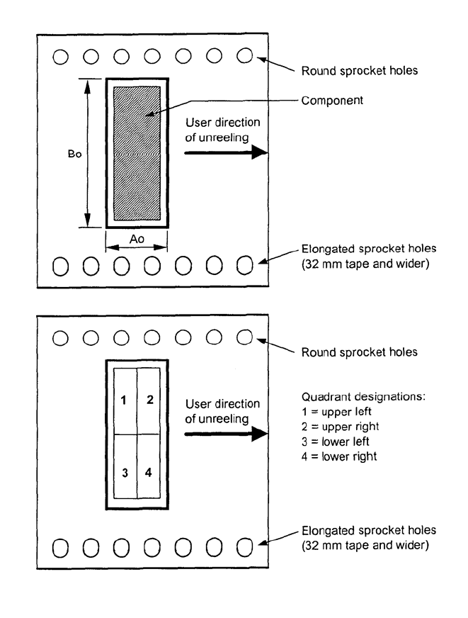
(e) The tape pocket quadrant designations that describe the taped orientation of components are shown
in Figure 1.
如图1所示,载体格子象限指定规定了元件卷装方向。
(f) For existing Component Packages use Figure 2 “Orientation Guide for Commonly Used Devices”.
现有的元件封装参照图2“常用器件定位指南”。
(g) If a package type is not contained in Figure 2, use the rules in the sequence shown in the following
flow chart (Figure 3) to determine the correct orientation of the component in the tape pocket.
如果封装类型没有包含在图 2 中,使用下列流程图(图 3 )中的顺序规则来确定的元件在载体格子中的正确方向。
EIA-481-D
Page
5
Left Intentionally Blank
本页空白
EIA-481-D
Page
6
Figure 1 -- Component orientation and quadrant designations 图 1- 元件定向和象限指定
圆形齿孔
元件
用户的取件方向
椭圆形齿孔(32 毫米以上带宽)
圆形齿孔
椭圆形齿孔(32 毫米以上带宽)
用户的取件方向
象限名称
左上角
右上角
左下角
右下角