EIA-481-D中文版----美国电子工业协会.pdf - 第16页
EIA-481-D Page 10 Figure 4-- 8 mm & 12 mm punched carrier tape dimensions 图 4--8 毫米 &12 毫米穿孔载体尺寸 See Section 4.0 for requirements (all dimensions in millimeters) 详见段落 4.0 规范 ( 所有的尺寸均以毫米为单位 ) Figure 5 -- Illustrat…
EIA-481-D
Page
9
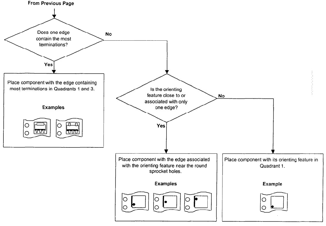
Figure 3-- Rules for determining orientation of component in tape pocket (2 of 2) 图 3-确定元件在
载体格子中方向的规则 (第 2 页,共 2 页)
续前页
其中的一边包含了
最多的端子吗?
是
是
否
否
放置元件时包含最多接线端的边在第 1
和第 3 象限。
例如
例如 例如
面向特征只与一边
接近或有关联吗?
放置元件时与面向特征关联的一边接近
圆形的齿孔侧。
放置元件时其面向特征在第 1 象限。
EIA-481-D
Page
10
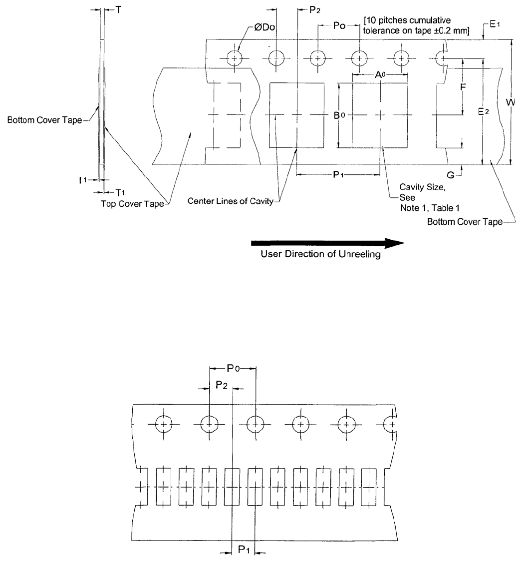
Figure 4-- 8 mm & 12 mm punched carrier tape dimensions 图 4--8 毫米&12 毫米穿孔载体尺寸
See Section 4.0 for requirements (all dimensions in millimeters)
详见段落 4.0 规范(所有的尺寸均以毫米为单位)
Figure 5 -- Illustration of 2 mm cavity pitch for 8 mm & 12 mm punched and embossed carrier,
P1. 图5--8毫米 & 12毫米穿孔载体和压纹载体2毫米格子间距图解, P1
See Tables 1 & 2 and requirement 4.3
详见表1 &2和段落4.3规范
底部的覆盖带
顶部的覆盖带
载体上 10 个间距的公差±0.2 毫米
格子的中心线
格子尺寸
见表 1 及注
意事项 1
底部的覆盖带
用户的取件方向
EIA-481-D
Page
11
Table 1 -- 8 & 12 mm punched carrier dimensions 表1--8 & 12 毫米穿孔载体尺寸
(all dimensions in millimeters)
(所有的尺寸均以毫米为单位)
Constant Dimensions 固定尺寸部分
Tape
Size
带宽
D
0
E
1
P
0
P
2
T
1
Max. G
Min.
R Ref. See
Note 2
见注意事项 2
8 mm &
12 mm
1.5+0.1
-0.0
1.75±
0.1
4.0
±0.1
2.0±0.05 0.1 0.75 25
Variable Dimensions 变动尺寸部分
Tape Size
带宽
E
2
Min
F P
1
W
Max
A
0
B
0
T
8 mm 6.25 3.5 ±
0.05
2.0±0.05
or
4.0±0.1
8.3
12 mm 10.25 5.5 ±
0.05
2.0 ± 0.05,
4.0±0.1 or
8.0±0.1
12.3
See
Note 1
见注意
事项 1
1.1 mm Maximum for Paper Base
Tape and 1.6 mm maximum for
Non-Paper Base Compositions.
纸基载体为最大 1.1 毫米,非纸基组合为最大
1.6 毫米。
See Note 2 and Requirement 4.3
详见注意事项 2 和段落 4.3 规范
Notes 注意事项
1. The cavity defined by A
0
, B
0
and T shall surround the component with sufficient clearance that:
格子的尺寸由 A
0
, B
0
和 T 定义,它包围着元件并留有充分的间隙:
a) the component does not protrude beyond either surface of the carrier tape.
元件不超出载体的任何一面。
b) the component can be removed from the cavity in a vertical direction without mechanical restriction,
after the top cover tape has been removed.
在去除顶部的覆盖带后,元件可以在垂直的方向上无任何机械障碍地从格子中取出。
c) rotation of the component is limited to 20°maximum (See Figure 8).
元件的转动范围限制在 20°以内(见图 8)。
d) lateral movement of the component is restricted to 0.5 mm maximum (See Figure 9).
元件水平方向上的移动量限制在 0.5 毫米以内(见图 9)。
e) see Addendum for standards relating to more precise taping requirements.
参照附录查找相关更多精确的卷装要求的标准。
2. The tape with or without components shall pass around R without damage (see Figure 11).
有无元件的载体应可无损地通过圆形 R(见图 11)。