EIA-481-D中文版----美国电子工业协会.pdf - 第20页
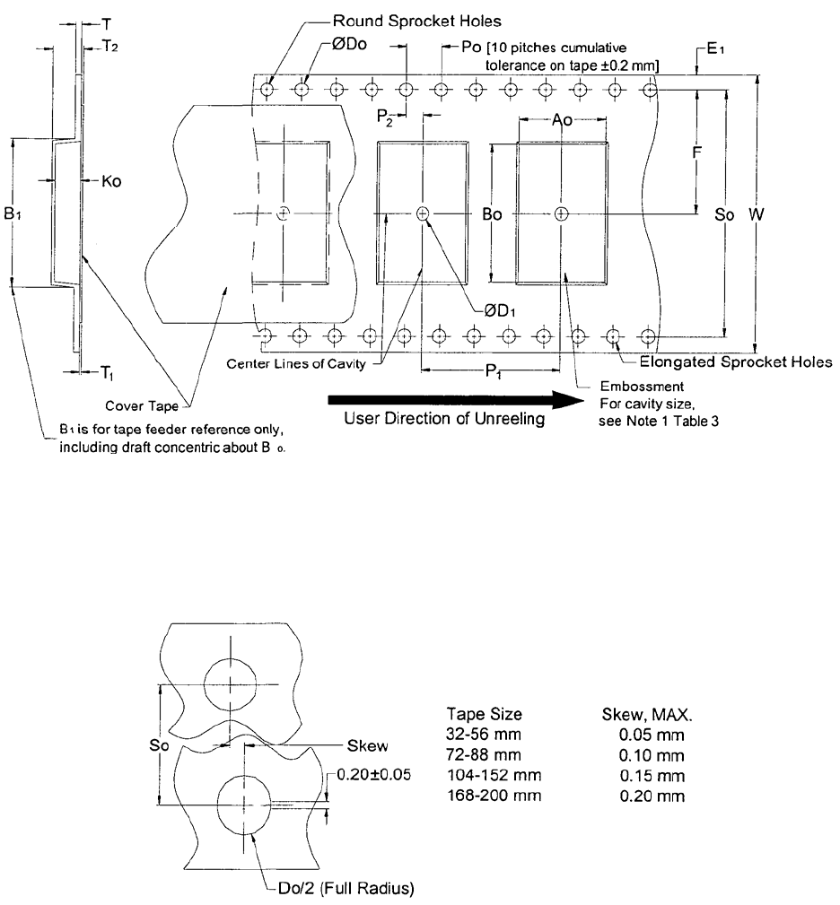
EIA-481-D Page 14 Figure 7 - 32,44,56,72,88,104, 120,136,152,168,184 and 200 mm em bossed carrier tape dimensions 图 7--32, 44, 56, 72, 88, 104, 120, 136, 152, 168, 184 和 200 毫米压纹载体尺寸 Detail, Elongation and Skew of Sprock…
EIA-481-D
Page
13
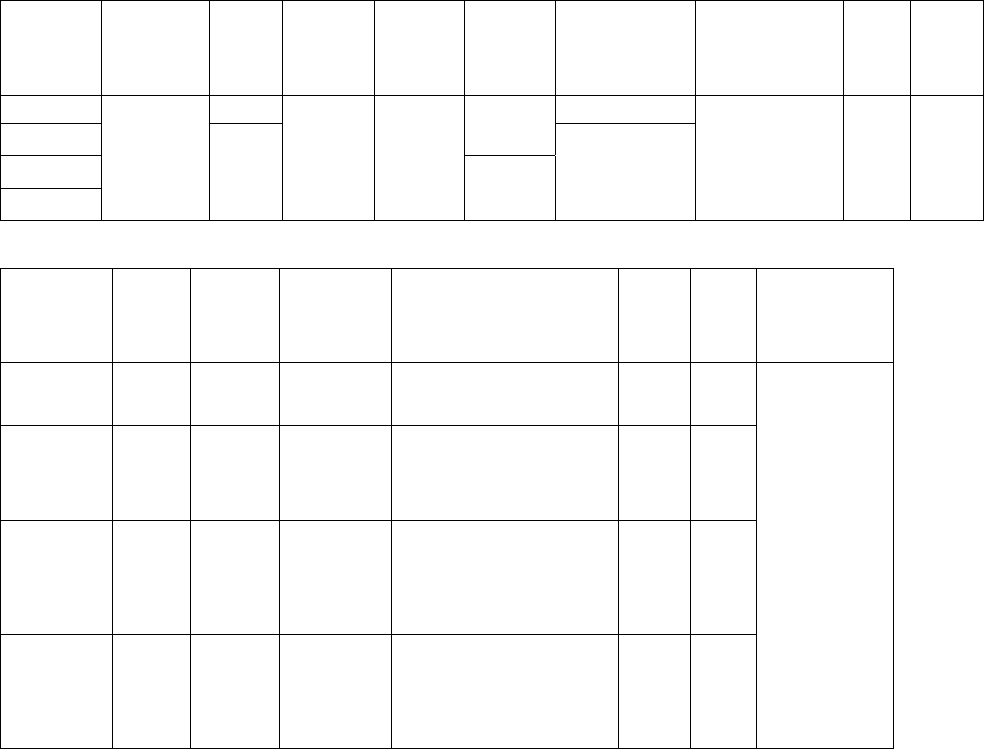
Table 2—8, 12, 16 & 24 mm embossed carrier dimensions 表2--8, 12, 16 & 24毫米压纹载体尺寸
Constant (for 2 or more widths) Dimensions
固定尺寸部分(用于2个以上的带度)
Tape
size
载体尺寸
D
0
D
1
Min
E
1
P
0
P
2
R Ref. See
Note 2
见注意事项 2
S
1
Min. See
Note 3.
见注意事项 3
T
Max
.
T
1
Max.
8 mm 1.0 25
12 mm
2.0±
0.05
16 mm
24 mm
1.5 +0.1
-0.0
1.5
1.75
±0.1
4.0
±0.1
2.0±
0.1
30
0.6 0.6 0.1
Variable Dimensions 变动尺寸部分
Tape
Size
带宽
B
1
Max.
E
2
Min.
F P
1
T
2
Max
W
Max
A
0
, B
0
&
K
0
8 mm 4.35 6.25
3.5±
0.05
2.0±0.05 or
4.0±0.10
2.5 8.3
12 mm 8.2 10.25
5.5±
0.05
2.0±0.05 or
4.0±0.1 or
8.0±0.1
6.5 12.3
16 mm 12.1 14.25 7.5
±0.1
4.0±0.1 to
12.0±0.1 in
4.0 increments
以 4.0 为增量
8.0 16.3
24 mm 20.1 22.25 11.5
±0.1
4.0±0.1 to
20.0±0.1 in
4.0 increments
以 4.0 为增量
12.0 24.3
See Note 1
见注意事项 1
Note 注意事项
1. The cavity defined by A
0
, B
0
and K
0
shall surround the component with sufficient clearance that:
格子的尺寸由 A
0
, B
0
和 K
0
定义,它包围着元件并留有充分的间隙:
(a) the component does not protrude above the top surface of the carrier tape.
元件不超出载体的顶面。
(b) the component can be removed form the cavity in a vertical direction without mechanical restriction,
after the top cover tape has been removed.
在去除顶部的覆盖带后,元件可以在垂直的方向上无任何机械障碍地从格子中取出。
(c) rotation of the component is limited to 20°maximum for 8 and 12 mm tapes and 10°maximum for 16
mm and 24 mm tapes (see Figure 8).
8 和 12 毫米的载体,元件的转动范围限制在 20°以内;16 和 24 毫米的载体限制在 10°以内(见图 8)。
(d) lateral movement of the component is restricted to 0.5 mm maximum for 8 mm and 12 mm wide tape
and to 1.0 mm maximum for 16 mm, 24 mm wide tape (see Figure 9).
8 和 12 毫米的载体,元件水平方向上的移动量限制在 0.5 毫米以内;16 和 24 毫米的载体限制在 1.0 毫米以内(见图 9)。
(e) see Addendum for standards relating to more precise taping requirements.
参照附录查找相关更多精确的卷装要求的标准。
2. The tape with or without components shall pass around R without damage (see Figure 11).
有无元件的载体应可无损地通过圆形 R(见图 11)。
3. If S1<1.0mm, there may not be enough area for cover tape to be properly applied (see paragraph 4.3(b)).
如果S1<1.0毫米,可能会没有足够的区域使覆盖带获得适当的封合(见段落4.3(b))。
EIA-481-D
Page
14
Figure 7 - 32,44,56,72,88,104,120,136,152,168,184 and 200 mm embossed carrier tape
dimensions 图7--32, 44, 56, 72, 88, 104, 120, 136, 152, 168, 184 和200毫米压纹载体尺寸
Detail, Elongation and Skew of Sprocket Holes
局部视图,齿孔的椭圆形及偏离
覆盖带
载体上 10 个间距的公差±0.2 毫米
格子的中心线
格子尺寸见表 3 及注意
事项 1
用户的取件方向
B1仅供载体进料器参考,包括同心
尺寸B0周围的拔模斜度。
压纹
椭圆形
齿孔
偏离
全径
带宽 最大偏离
EIA-481-D
Page
15
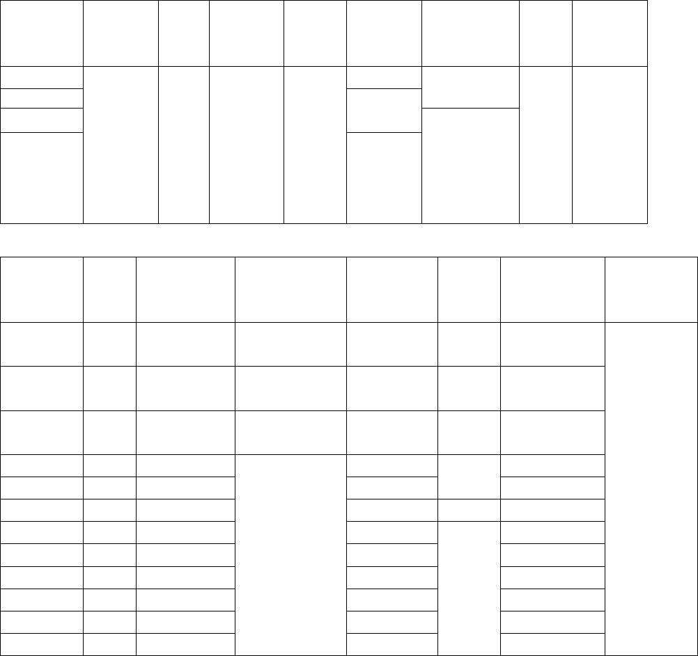
Table 3--32, 44, 56, 72, 88, 104, 120, 136, 152, 168, 184 & 200 mm embossed carrier
dimensions 表 3--32, 44, 56, 72, 88, 104, 120, 136, 152, 168, 184 & 200 毫米压纹载体尺寸
Constant Dimensions (for 2 or more widths)
固定尺寸部分(用于 2 个以上的带度)
Tape size
带宽
D
0
D
1
Min
E
1
P
0
P
2
R Ref. See
Note 2
见注意事项 2
T
Max.
T
1
Max.
32 mm
2.0±0.1
44 mm
50
56 mm
2.0±
0.15
72 mm
through
200 mm
72 到 200 毫
米
1.5 +0.1
-0.0
2.0
1.75±
0.10
4.0±
0.1
2.0±0.2
75
0.6 0.1
Variable Dimensions 变动尺寸部分
Tape size
带宽
B
1
Max.
F P
1
(in 4.0
increments
以 4.0 为增量)
S
0
T
2
Max.
W A
0
, B
0
&
K
0
32 mm 23.0
14.2±0.10
4.0±0.1
to 32.0±0.1
28.4±0.1
12.0
32.0±0.3
44 mm 35.0
20.2±0.15
4.0±0.1
to 44.0±0.1
40.4±0.1
16.0
44.0±0.3
56 mm 46.0
26.2±0.15
4.0±0.1
to 56.0±0.1
52.4±0.1
20.0
56.0±0.3
72 mm 60.0
34.2±0.30 68.4±0.1 72.0±0.3
88 mm 76.0
42.2±0.30 84.4±0.1
30.0
88.0±0.3
104 mm 91.0
50.2±0.35 100.4±0.1
35.0
104.0±0.3
120 mm 107.0
58.2±0.35 116.4±0.1 120.0±0.3
136 mm 123.0
66.2±0.40 132.4±0.1 136.0±0.3
152 mm 139.0
74.2±0.40 148.4±0.1 152.0±0.3
168 mm 153.0
82.2±0.45 164.4±0.1 168.0±0.3
184 mm 169.0
90.2±0.45 180.4±0.1 184.0±0.3
200 mm 185.0
98.2±0.50
4.0±0.1 to
72.0±0.1
196.4±0.1
40.0
200.0±0.3
See Note 1
见注意事项 1
Note 注意事项
1. The cavity defined by A
0
, B
0
and K
0
shall surround the component with sufficient clearance that:
格子的尺寸由 A
0
, B
0
和 K
0
定义,它包围着元件并留有充分的间隙:
(a) the component does not protrude above the top surface of the carrier tape.
元件不超出载体的顶面。
(b) the component can be removed from the cavity in a vertical direction without mechanical restriction,
after the top cover tape has been removed.
在去除顶部的覆盖带后,元件可以在垂直的方向上无任何机械障碍地从格子中取出。
(c) rotational limits of the component in the pocket are illustrated in Figure8.
元件在格子中的转动范围限制在图 8 中有说明。
(d) lateral movement of the component is restricted to 1.0 mm maximum (See Figure 9).
元件水平方向上的移动量限制在 1.0 毫米以内(见图 9)
2. The tape with or without components shall pass around R without damage (see Figure 11).
有无元件的载体应可无损地通过圆形 R(见图 10)。