EIA-481-D中文版----美国电子工业协会.pdf - 第22页
EIA-481-D Page 16 Figure 8 -- Maximum component rota tion for punched and embossed carrier 图 8— 穿孔和压纹载体 中元件的最大旋转 Figure 9 -- Maximum lateral movement for punched and embossed carrier 图 9— 穿孔和压纹载体中的 元件最大移动 Figure 10 -- Ba…
EIA-481-D
Page
15
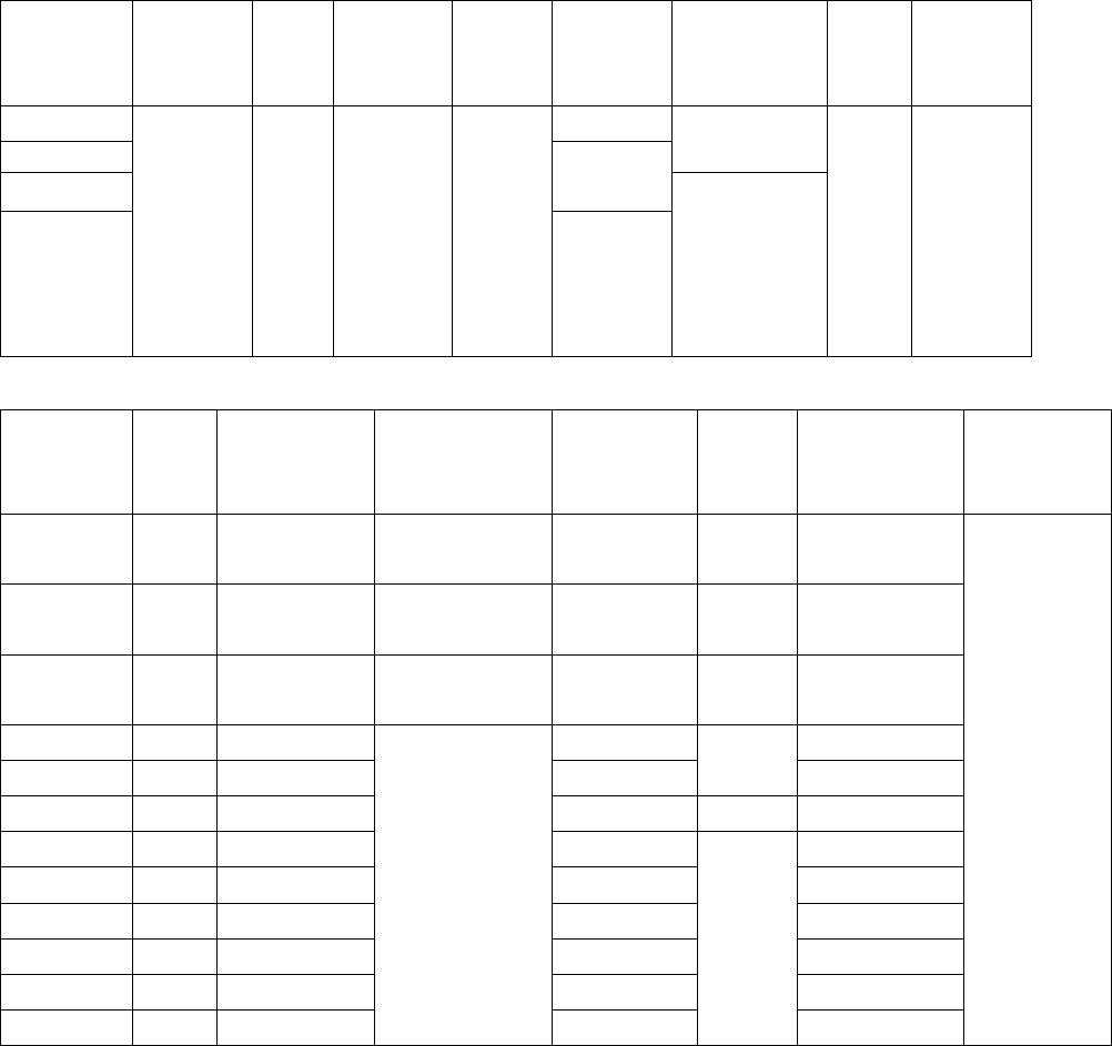
Table 3--32, 44, 56, 72, 88, 104, 120, 136, 152, 168, 184 & 200 mm embossed carrier
dimensions 表 3--32, 44, 56, 72, 88, 104, 120, 136, 152, 168, 184 & 200 毫米压纹载体尺寸
Constant Dimensions (for 2 or more widths)
固定尺寸部分(用于 2 个以上的带度)
Tape size
带宽
D
0
D
1
Min
E
1
P
0
P
2
R Ref. See
Note 2
见注意事项 2
T
Max.
T
1
Max.
32 mm
2.0±0.1
44 mm
50
56 mm
2.0±
0.15
72 mm
through
200 mm
72 到 200 毫
米
1.5 +0.1
-0.0
2.0
1.75±
0.10
4.0±
0.1
2.0±0.2
75
0.6 0.1
Variable Dimensions 变动尺寸部分
Tape size
带宽
B
1
Max.
F P
1
(in 4.0
increments
以 4.0 为增量)
S
0
T
2
Max.
W A
0
, B
0
&
K
0
32 mm 23.0
14.2±0.10
4.0±0.1
to 32.0±0.1
28.4±0.1
12.0
32.0±0.3
44 mm 35.0
20.2±0.15
4.0±0.1
to 44.0±0.1
40.4±0.1
16.0
44.0±0.3
56 mm 46.0
26.2±0.15
4.0±0.1
to 56.0±0.1
52.4±0.1
20.0
56.0±0.3
72 mm 60.0
34.2±0.30 68.4±0.1 72.0±0.3
88 mm 76.0
42.2±0.30 84.4±0.1
30.0
88.0±0.3
104 mm 91.0
50.2±0.35 100.4±0.1
35.0
104.0±0.3
120 mm 107.0
58.2±0.35 116.4±0.1 120.0±0.3
136 mm 123.0
66.2±0.40 132.4±0.1 136.0±0.3
152 mm 139.0
74.2±0.40 148.4±0.1 152.0±0.3
168 mm 153.0
82.2±0.45 164.4±0.1 168.0±0.3
184 mm 169.0
90.2±0.45 180.4±0.1 184.0±0.3
200 mm 185.0
98.2±0.50
4.0±0.1 to
72.0±0.1
196.4±0.1
40.0
200.0±0.3
See Note 1
见注意事项 1
Note 注意事项
1. The cavity defined by A
0
, B
0
and K
0
shall surround the component with sufficient clearance that:
格子的尺寸由 A
0
, B
0
和 K
0
定义,它包围着元件并留有充分的间隙:
(a) the component does not protrude above the top surface of the carrier tape.
元件不超出载体的顶面。
(b) the component can be removed from the cavity in a vertical direction without mechanical restriction,
after the top cover tape has been removed.
在去除顶部的覆盖带后,元件可以在垂直的方向上无任何机械障碍地从格子中取出。
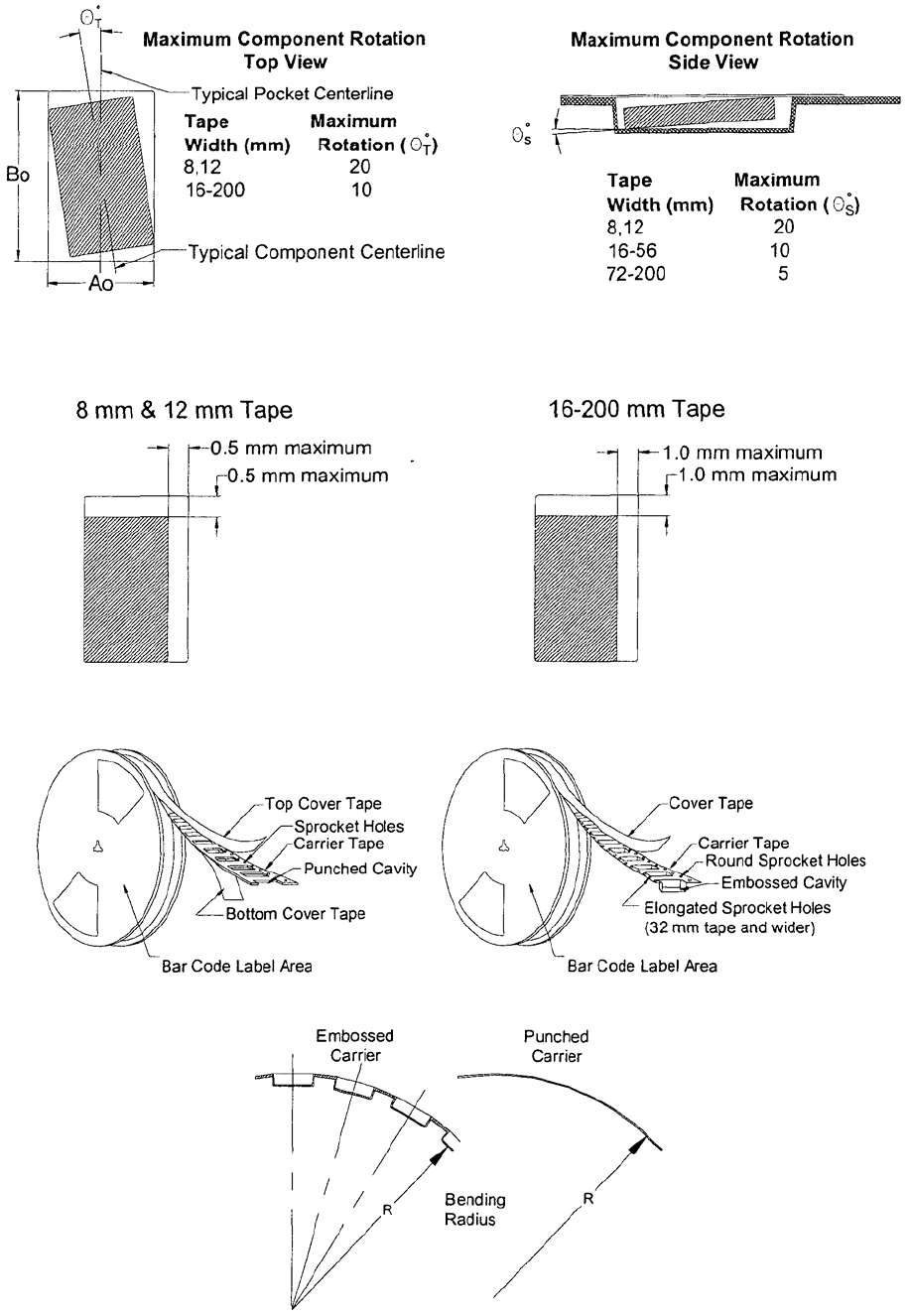
(c) rotational limits of the component in the pocket are illustrated in Figure8.
元件在格子中的转动范围限制在图 8 中有说明。
(d) lateral movement of the component is restricted to 1.0 mm maximum (See Figure 9).
元件水平方向上的移动量限制在 1.0 毫米以内(见图 9)
2. The tape with or without components shall pass around R without damage (see Figure 11).
有无元件的载体应可无损地通过圆形 R(见图 10)。
EIA-481-D
Page
16
Figure 8 -- Maximum component rotation for punched and embossed carrier 图 8—穿孔和压纹载体
中元件的最大旋转
Figure 9 -- Maximum lateral movement for punched and embossed carrier 图 9—穿孔和压纹载体中的
元件最大移动
Figure 10 -- Bar code label area for punched and embossed carrier 图 10—穿孔和压纹载体条形码区域
Figure 11-- Bending radius for punched and embossed carrier 图 11—穿孔和压纹载体的弯曲半径
元件的最大旋转 顶视图
典型格子中心线
带度 最大旋转
典型元件中心线
元件的最大旋转 侧视图
带度 最大旋转
8毫米&12毫米载体 16-200毫米载体
最大 0.5 毫米
最大 0.5 毫米 最大 1.0 毫米
最大 1.0 毫米
顶部覆盖带
齿孔
载体
穿孔格子
底部的覆盖带
条形码区域
覆盖带
载体
圆形齿孔
压纹格子
椭圆形齿孔(32
毫米以上带宽)
条形码区域
压纹载体 穿孔载体
弯曲半径
EIA-481-D
Page
17
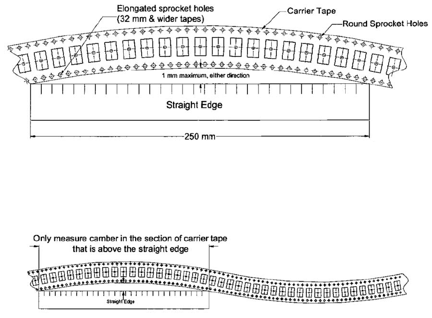
Figure12 -- Maximum camber for punched and embossed carrier 图 12 – 穿孔和压纹载体的最大弯曲度
To accurately measure camber, place the starting end of the carrier tape sample on the left end of the measurement fixture or
straight edge. Moving to the right, measure the allowable camber at the highest point between where the left edge and the
right edge of the carrier tape make contact with the measurement fixture or straight edge.
要精确测量弯曲度,将载体样品的开始端放置在测量制具或直边的左侧。移动到右侧,在载体与测试制具或直边接触的左、右侧之间的
最高点测量允许的弯曲度。
载体
椭圆形齿孔(32
毫米以上带宽)
圆形齿孔
在任一方向上最大 1 毫米
直边
直边
只在高出直边的载体部分测量弯曲度