Printer 600 Pneumatic Module.pdf - 第10页
31( 80$7,&0 2'8 /( 31(80$7,& '(9,&(6 24.10 Technical Reference Manual Chapter Issue 3 May 03 Double Acting Cylinders The force exert ed by the compressed air i s required to move the pist on in ea…
31(80$7,&02'8/(
31(80$7,&'(9,&(6
Chapter Issue 3 May 03 Technical Reference Manual 24.9
Single Acting
Cylinders
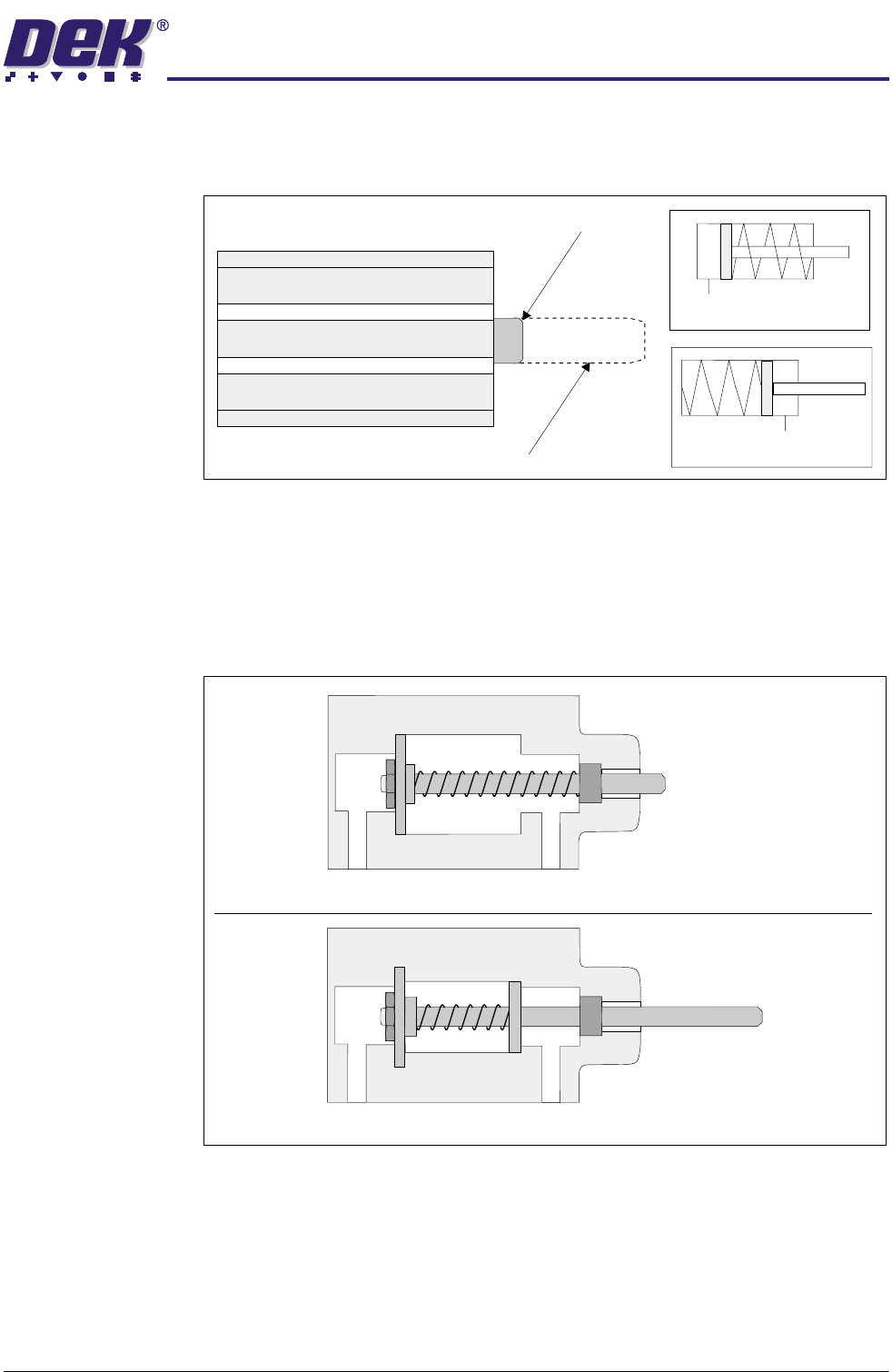
Single acting cylinders only require compressed air for movement in one
direction. The movement of the piston in the other direction is effected by a
spring. There are two versions of the single acting cylinder fitted to the machine.
Figure 24-7 Single Acting Cylinder and Symbol
Version 1 - With air connected to Port A, compressed air extends the piston.
When the air is disconnected the spring retracts the piston (cylinder rest state).
Version 2 - With air connected to Port B, compressed air retracts the piston.
When the air is disconnected the spring extends the piston (cylinder rest state).
Figure 24-8 Single Acting Cylinder Cross Section
Extended
Retracted
Version 1 (Symbol)
Version 2 (Symbol)
Port A
Port B
Version 1
Version 2
Port A
Port B
31(80$7,&02'8/(
31(80$7,&'(9,&(6
24.10 Technical Reference Manual Chapter Issue 3 May 03
Double Acting
Cylinders
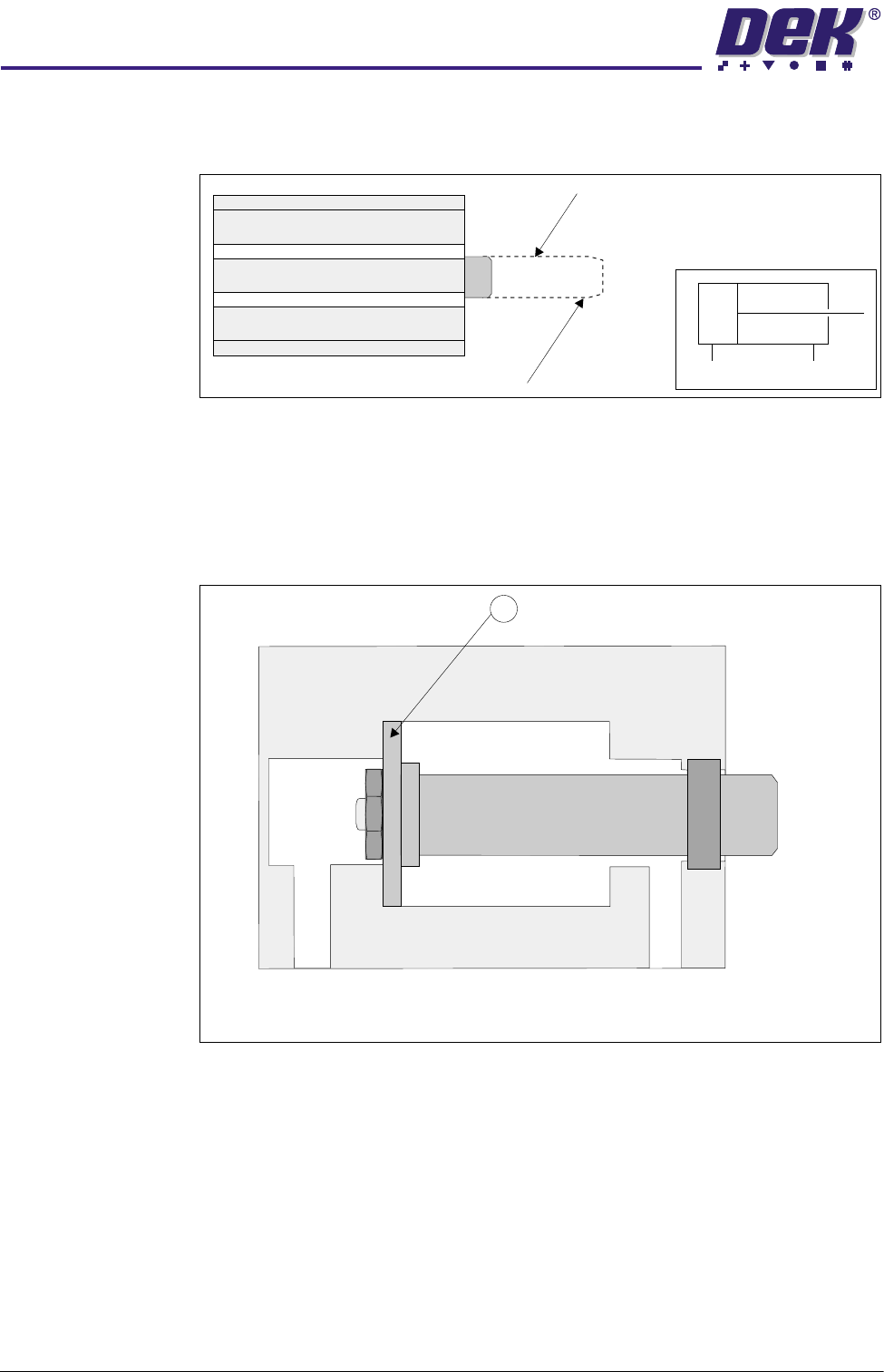
The force exerted by the compressed air is required to move the piston in each
direction. A definite force is applied on both advance and return movements.
Figure 24-9 Double Acting Cylinder and Symbol
Double acting cylinders allow work to be performed in both directions. Air
entering at Port A acts against the valve plate (1) driving it backwards, retracting
the piston to which it is attached and exhausting air through Port B. To extend
the piston air enters Port B and the process repeats in the other direction.
Figure 24-10 Double Acting Cylinder Cross Section
Piston Extended
Piston Retracted
Symbol
1
Port
A
Port
B
31(80$7,&02'8/(
31(80$7,&'(9,&(6
Chapter Issue 3 May 03 Technical Reference Manual 24.11
Manifold Solenoid
Valves Type 5/2
A body mounted solenoid valve, type 5/2 is fitted to the manifold. This type of
solenoid is used with a double acting cylinder.
NOTE
Although the board stop is not a double acting cylinder, a type 5/2 solenoid is
used in this instance to be in place for the option of a remote board stop.
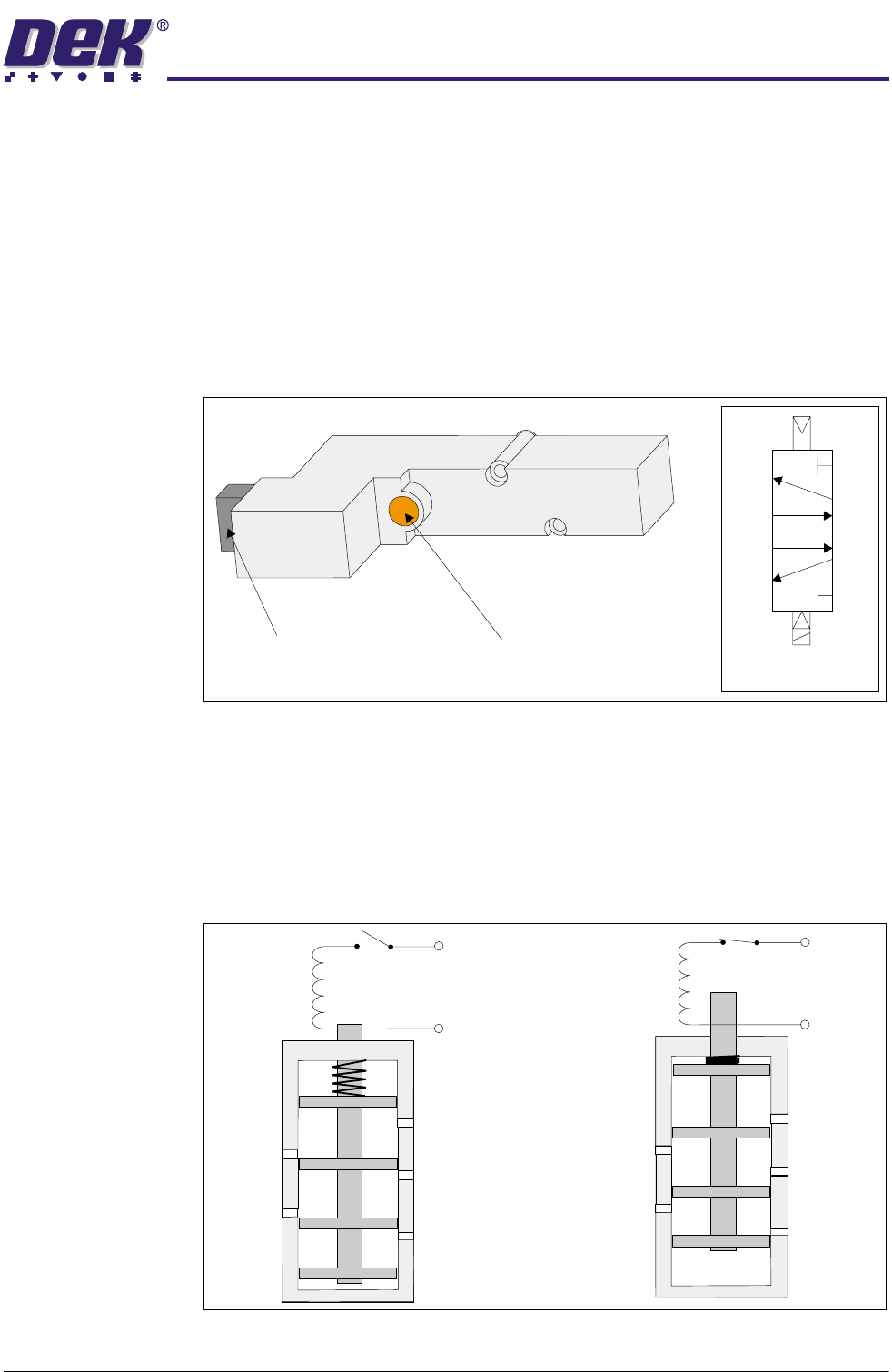
The solenoid controls the distribution of compressed air to a pneumatic cylinder
to provide mechanical work. The solenoid is activated by a 24V signal which is
identified by an illuminated red Led within the solenoid.
An orange manual override button allows the solenoid to be activated to test
correct operation.
Figure 24-11 Solenoid and Symbol
In the rest state, with the solenoid switched off, the plunger (armature) is held
out under spring pressure, connecting the ports as shown in Solenoid Cross
Section figure.
When the solenoid is switched on, the plunger is pulled upwards against the
spring. This causes the port connections to change as shown in figure.
Figure 24-12 Solenoid Cross Section
Symbol
3
2
4
1
5
Red LED
(inside solenoid unit)
Manual Override Button
3
3
1
1
5
5
4 (A)
4 (A)
2 (B)
2 (B)
+ 24V
0V
+ 24V
0V