Printer 600 Pneumatic Module.pdf - 第15页
31(80$7,& 02'8/( 31(80$7,& '(9,&(6 Chapter Issue 3 May 03 Technical Reference Manual 24.15 V enturi V acuum Pump The pump provides the sucti on required for vacuum tooling. Figure 24-19 V enturi V…
31(80$7,&02'8/(
31(80$7,&'(9,&(6
24.14 Technical Reference Manual Chapter Issue 3 May 03
Pressure Relief
Valve
The pressure relief valve is fitted in parallel with the screen cleaner solvent unit
and manually set to either 1 bar (Blue USC) or 0.1 bar (Vortex USC). If the
compressed air supply to the solvent unit exceeds 1 bar, the pressure relief
valve operates venting to atmosphere via a silencer, thus preventing the solvent
unit from becoming over pressurized.
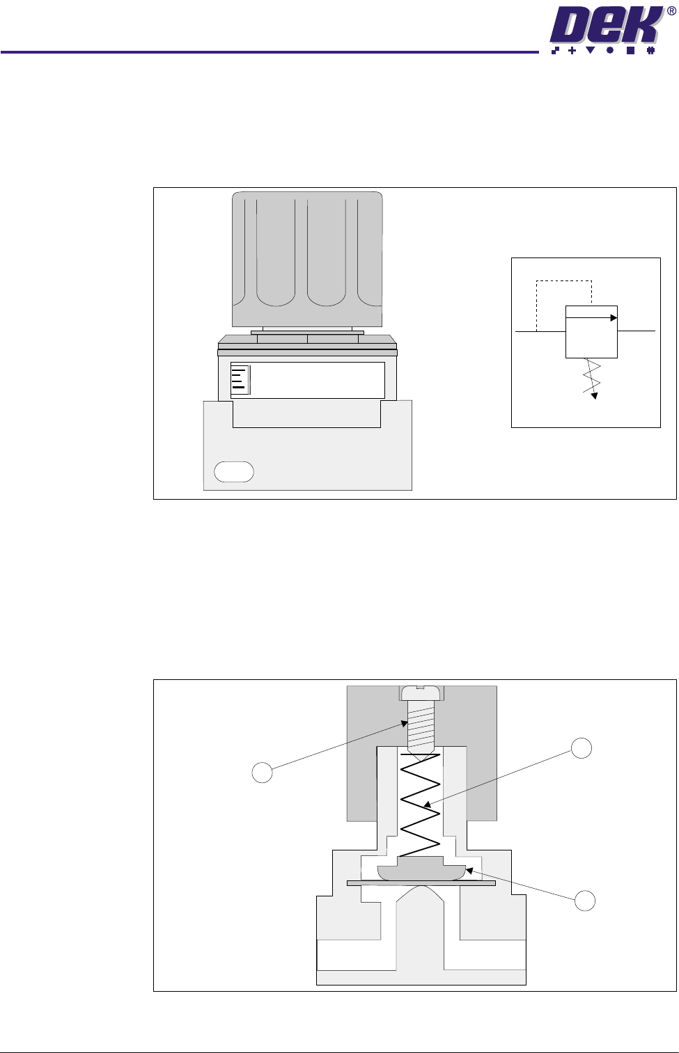
Figure 24-17 Pressure Relief Valve and Symbol
The operating pressure is set by means of compressing/extending a spring (1)
against a diaphragm (2) by adjustment of a set screw (3). The valve is normally
closed, with compressed air at Port A being insufficient to lift the diaphragm (2).
When compressed air above the set level enters the valve, it acts against the
spring pressure lifting the diaphragm and venting through Port B to atmosphere
via a silencer.
Figure 24-18 Pressure Relief Valve Cross Section
Z0
1/4
PRESSURE CONTROL VALVE
MODEL
AP 100
Symbol
Port
A
Port
B
1
2
3
31(80$7,&02'8/(
31(80$7,&'(9,&(6
Chapter Issue 3 May 03 Technical Reference Manual 24.15
Venturi Vacuum
Pump
The pump provides the suction required for vacuum tooling.
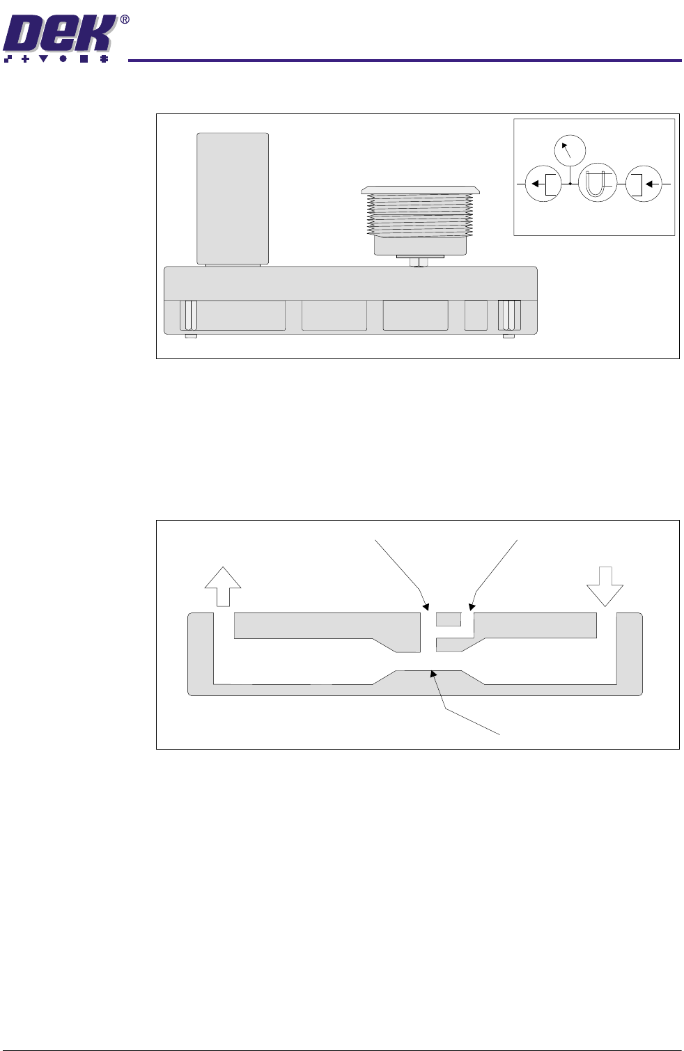
Figure 24-19 Venturi Vacuum Pump and Symbol
The device consists essentially of a convergence in a pipe line, followed by a
short parallel-sided throat and a divergence. Air at the inlet is accelerated
through the throat to the exhaust. The flow of air through the throat causes a
suction at the vacuum port. The faster the flow of air through the throat the
greater the vacuum.
Figure 24-20 Venturi Vacuum Pump Cross Section
Symbol
P
Inlet
Exhaust
Vacuum Gauge
Throat
31(80$7,&02'8/(
31(80$7,&'(9,&(6
24.16 Technical Reference Manual Chapter Issue 3 May 03
Rotary Actuator The rotary actuator produces a rotary output from a compressed air input. This
drive is used via a rotary arm, to rotate the remote board stop through 90
degrees.
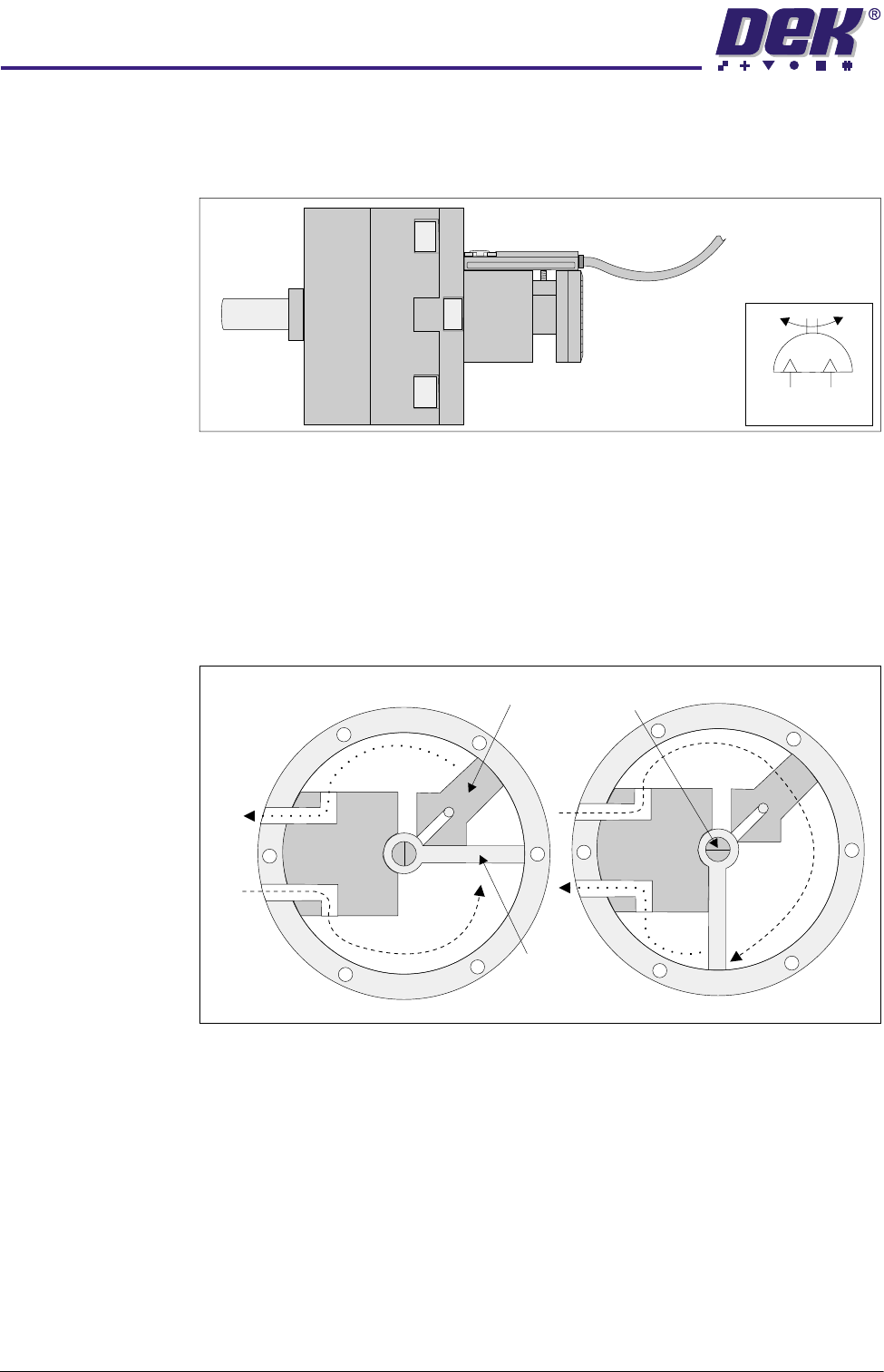
Figure 24-21 Rotary Actuator and Symbol
In the rest state air is supplied to Port A with Port B venting. The vane is driven
anti-clockwise against the stop, turning the drive shaft. On selection the air
supply is switched to Port B with Port A venting. This drives the vane and the
drive shaft clockwise through 90 degrees, producing the rotary drive. This is
the mode of operation when the remote board stop is fitted to the right hand side
of the rising table.
Figure 24-22 Rotary Actuator Cross Section
When the remote board stop is fitted to the left hand side of the rising table, the
air supplies to Port A and Port B are swapped over. In the rest state air is
supplied to Port B with Port A venting. The vane is driven clockwise, turning the
drive shaft. On selection the air supply is switched to Port A with Port B venting.
This drives the vane and the drive shaft anti-clockwise through 90 degrees,
against the stop, producing the rotary drive.
Symbol
Stop
Drive
Shaft
Vane
Port
B
Port
A