Printer 600 Pneumatic Module.pdf - 第6页
31( 80$7,&0 2'8 /( 31(80$7,& '(9,&(6 24.6 Technical Reference Manual Chapter Issue 3 May 03 Filter The compressed air fi lter removes any cont aminant s, in additio n to any water which has alread…
31(80$7,&02'8/(
31(80$7,&'(9,&(6
Chapter Issue 3 May 03 Technical Reference Manual 24.5
PNEUMATIC DEVICES
Regulator
Assemblies
There is a minimum of one and a maximum of five regulator assemblies fitted
to the machine as follows:
• Mains Air Input
• Paste Dispenser (option)
• Screen Cleaner Solvent Tank (option)
• ProFlow Software Controlled Air Regulator
• Board Clamps (option)
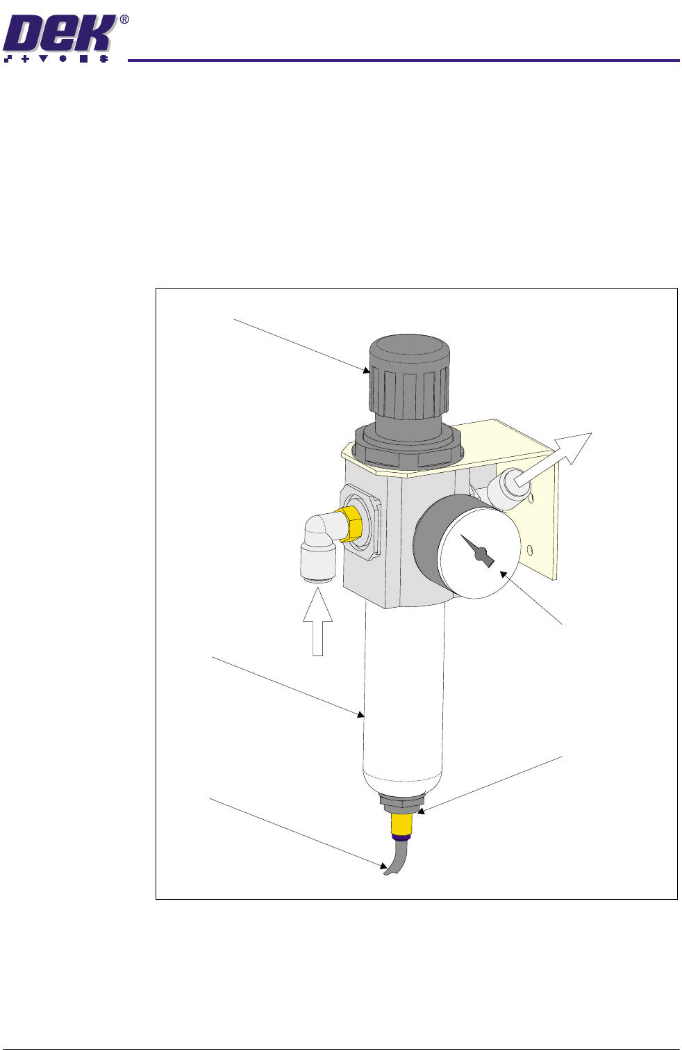
Figure 24-3 Mains Air Regulator Assembly
Filter
Drain
Drain Empty Valve
Pressure Sensor and Gauge
Regulator
Air In
Air Out
31(80$7,&02'8/(
31(80$7,&'(9,&(6
24.6 Technical Reference Manual Chapter Issue 3 May 03
Filter The compressed air filter removes any contaminants, in addition to any water
which has already condensed, from the compressed air flowing through it. The
filter is housed in a single unit incorporating an automatic drain and a pressure
regulator.
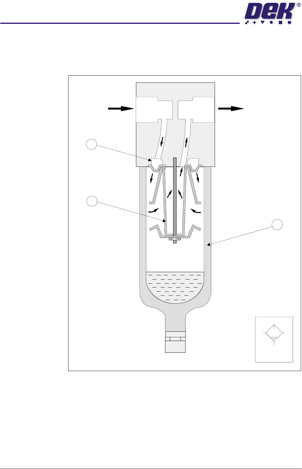
Figure 24-4 Cross Section and Symbol
The compressed air enters the filter bowl (2) through the guide slots (1) and is
rotated. Liquid particles and the dirt particles, which are larger than the mesh
size of the filter (3), separate centrifugally and collect in the lower part of the
filter bowl. A differential pressure type automatic drain removes the collected
condensate via a drain tube.
Air In
Air Out
1
3
2
Symbol
31(80$7,&02'8/(
31(80$7,&'(9,&(6
Chapter Issue 3 May 03 Technical Reference Manual 24.7
Regulator The regulator keeps the operation pressure virtually constant regardless of
fluctuations in line pressure and air consumption.
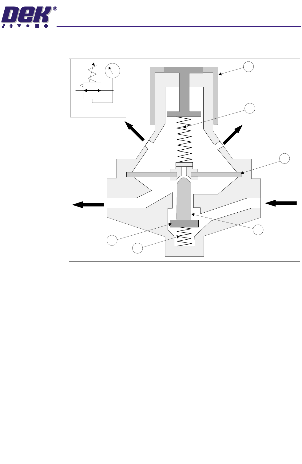
Figure 24-5 Regulator Cross Section and Symbol
The input pressure must always be higher than the output pressure. The output
pressure acts on one side of the diaphragm (1). A spring (2) acts on the other
side adjusted by knob (3).
The system is at equilibrium when the pressure at the outlet acting on the
diaphragm equals the spring (2) pressure opposing it.
If the output pressure increases, the upward force on the diaphragm increases
causing the valve (4) to close, thus reducing the throughput until output is again
at equilibrium with the spring force.
If (due to an increase in consumption) the output pressure drops and the spring
force exceeds the upward force on the diaphragm, valve (4) opens increasing
the throughput.
Regulation of the preset output pressure is a continual opening and closing of
the valve seat. To prevent flutter, spring damping (5) is provided below the valve
disc (6). If the output pressure increases considerably, the diaphragm is
pressed against the spring, the centrepiece opens and the compressed air flows
to atmosphere through the vent holes.
1
2
3
4
5
6
Vent Hole
Outlet
Inlet
Vent Hole
Symbol