Printer 600 Pneumatic Module.pdf - 第7页
31(80$7,& 02'8/( 31(80$7,& '(9,&(6 Chapter Issue 3 May 03 Technical Reference Manual 24.7 Regulator The regulat or keep s the operation pr essure vir tually co nstant regardl ess of fluctuat ions …
31(80$7,&02'8/(
31(80$7,&'(9,&(6
24.6 Technical Reference Manual Chapter Issue 3 May 03
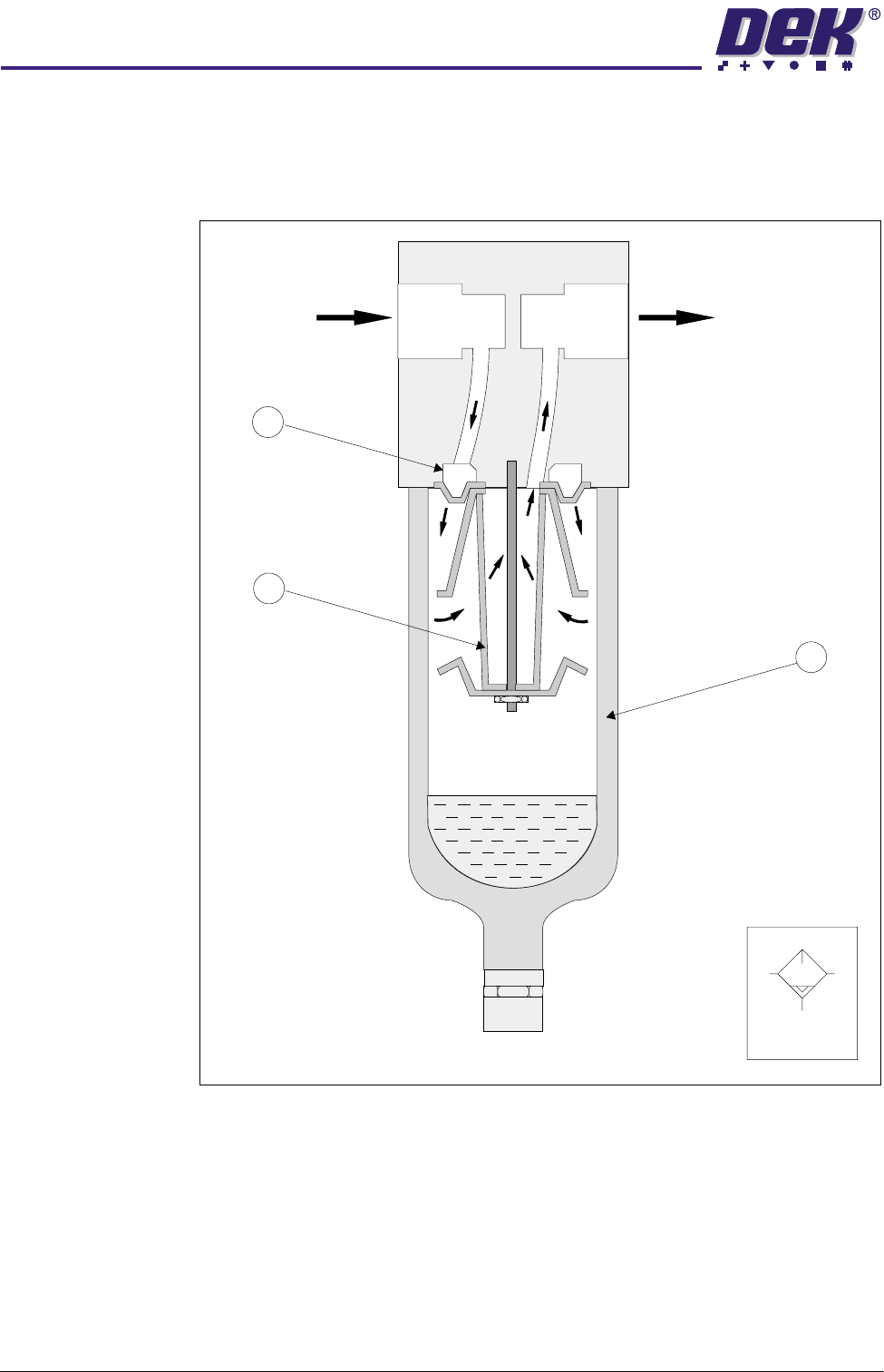
Filter The compressed air filter removes any contaminants, in addition to any water
which has already condensed, from the compressed air flowing through it. The
filter is housed in a single unit incorporating an automatic drain and a pressure
regulator.
Figure 24-4 Cross Section and Symbol
The compressed air enters the filter bowl (2) through the guide slots (1) and is
rotated. Liquid particles and the dirt particles, which are larger than the mesh
size of the filter (3), separate centrifugally and collect in the lower part of the
filter bowl. A differential pressure type automatic drain removes the collected
condensate via a drain tube.
Air In
Air Out
1
3
2
Symbol
31(80$7,&02'8/(
31(80$7,&'(9,&(6
Chapter Issue 3 May 03 Technical Reference Manual 24.7
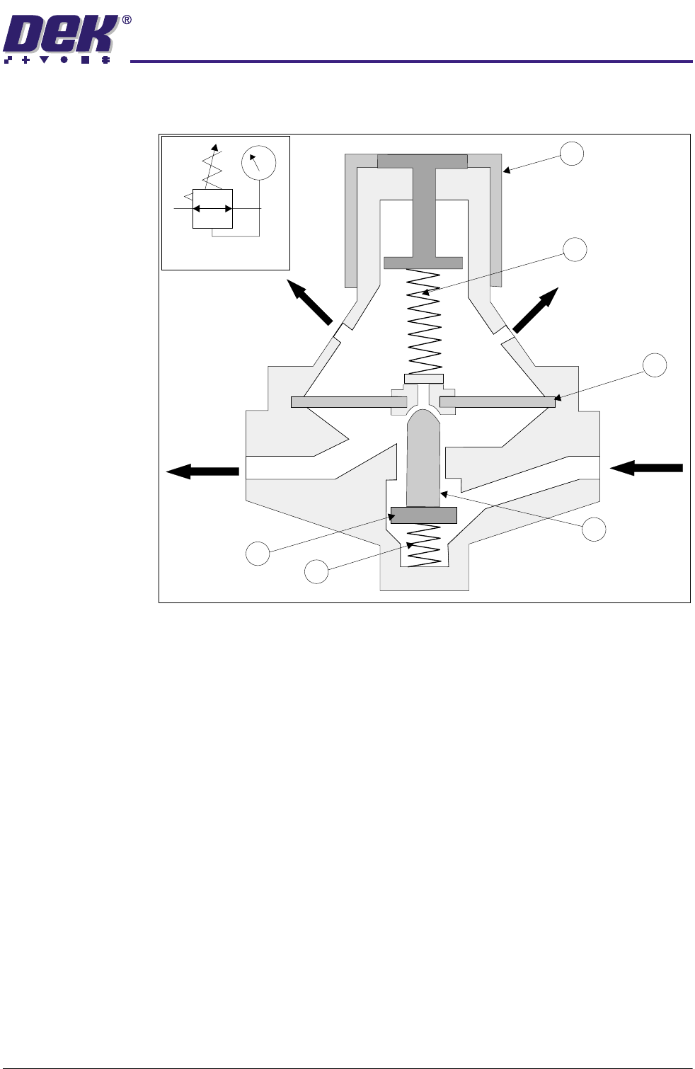
Regulator The regulator keeps the operation pressure virtually constant regardless of
fluctuations in line pressure and air consumption.
Figure 24-5 Regulator Cross Section and Symbol
The input pressure must always be higher than the output pressure. The output
pressure acts on one side of the diaphragm (1). A spring (2) acts on the other
side adjusted by knob (3).
The system is at equilibrium when the pressure at the outlet acting on the
diaphragm equals the spring (2) pressure opposing it.
If the output pressure increases, the upward force on the diaphragm increases
causing the valve (4) to close, thus reducing the throughput until output is again
at equilibrium with the spring force.
If (due to an increase in consumption) the output pressure drops and the spring
force exceeds the upward force on the diaphragm, valve (4) opens increasing
the throughput.
Regulation of the preset output pressure is a continual opening and closing of
the valve seat. To prevent flutter, spring damping (5) is provided below the valve
disc (6). If the output pressure increases considerably, the diaphragm is
pressed against the spring, the centrepiece opens and the compressed air flows
to atmosphere through the vent holes.
1
2
3
4
5
6
Vent Hole
Outlet
Inlet
Vent Hole
Symbol
31(80$7,&02'8/(
31(80$7,&'(9,&(6
24.8 Technical Reference Manual Chapter Issue 3 May 03
Gauge Each regulator assembly has a gauge to indicate the operating pressure. Each
gauge has a scale to read both psi and bar, except the mains air input gauge
which reads MPa. 1bar = 0.1MPa.
Sensor An adjustable pressure sensor, part of the mains air regulator assembly and set
to 3bar, senses whether the compressed air input is at the minimum level
required. See Sensors and Motors Chapter for further information.
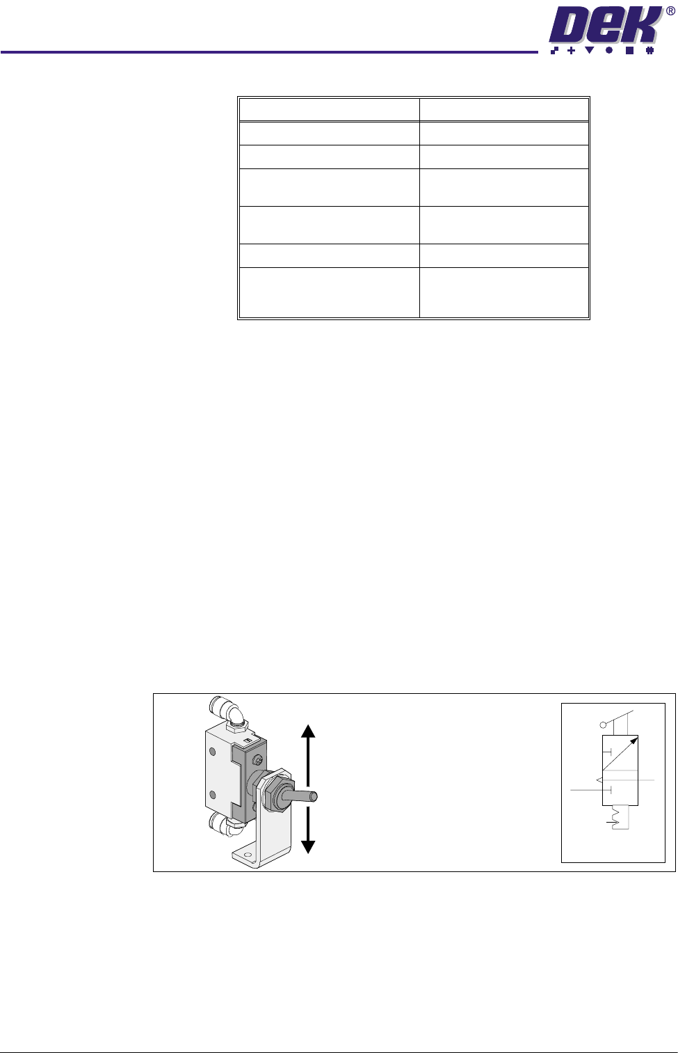
Toggle Switch The toggle switch acts as a two way manual switching device for activating and
de-activating the chase screen clamps.
NOTE
The toggle switch is not fitted to all machines.
Activating the switch (down position) connects the compressed air flow to Port
A of each of the four single acting cylinders (version 1 type).
De-activating the toggle switch (up position) cuts off the compressed air to each
actuator, automatically retracting the piston by spring action.
Figure 24-6 Toggle Switch
Regulator Setting
Main Air Input 5 bar nominal
Paste Dispenser 3 bar (43 psi) maximum
Screen Cleaner Solvent
(Blue USC)
1 bar (14.5 psi) maximum
Screen Cleaner Solvent
(Vortex)
0.1 bar
Board Clamps 4.5 bar (62.25psi) nominal
ProFlow - Software Regulator
ProFlow Idle Pressure
ProFlow Paste Pressure
0.2 bar
0.2 - 4 bar
Symbol
De-activate Clamps (OFF)
Activate Clamps (ON)
(Switch Position)