Printer 600 Pneumatic Module.pdf - 第4页
31( 80$7,&0 2'8 /( 0(&+$1 ,&$/'(7$ ,/ 24.4 Technical Reference Manual Chapter Issue 3 May 03 MECHANICAL DET AIL Manifold The manif old distri butes th e compressed air input dir ectly t o the pneu…
31(80$7,&02'8/(
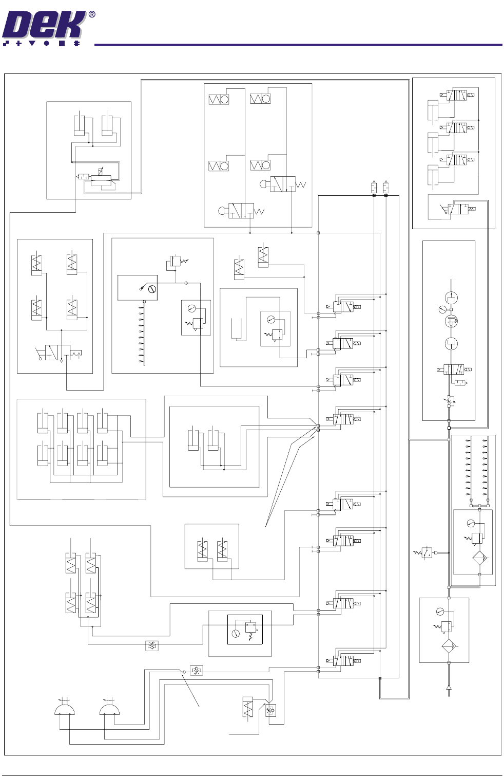
31(80$7,&6&+(0$7,&
Chapter Issue 3 May 03 Technical Reference Manual 24.3
PNEUMATIC SCHEMATIC
Remote Board Stop
(optional)
One connection
made at any
time
One connection
made at any
time
5/2
5/2
5/2
5/2
3/2
3/2
3/2
3/2
Mains Air In
at 4.5 Bar
Minimum
AB
AB
ABAB
A
BA BA BA B
In
In
In
ASM Screen Clamps
Board Clamps
Screen Clean
Squeegee Bar
(optional)
Screen Clamps - Standard
In
Out
Out
In
Out
Out
Out
Lid Bolt
Lid Bolt
Paste Dispense
R
P
Air Ioniser (optional)
Venturi Vacuum (optional)
High Throughput Conveyor
Vacuum
Tooling
Pressure Sensor
Filter/Reg Assy
Filter/Reg Assy
ASM Rail Clamp
Rail Clamps
Left
Screen Clamps
Under Screen
Cleaner (optional)
Wet
Clean
Solvent
Tank
Reg Assy
Reg Assy
Reg Assy
Relief
Valve
Screen Clamps - ELA 0.1 - ELA 0.2
ProFlow + SCAR
(optional)
Rail Clamps
Right
When used
for L-R
Board
Transfer
When used
for R-L
Board
Transfer
31(80$7,&02'8/(
0(&+$1,&$/'(7$,/
24.4 Technical Reference Manual Chapter Issue 3 May 03
MECHANICAL DETAIL
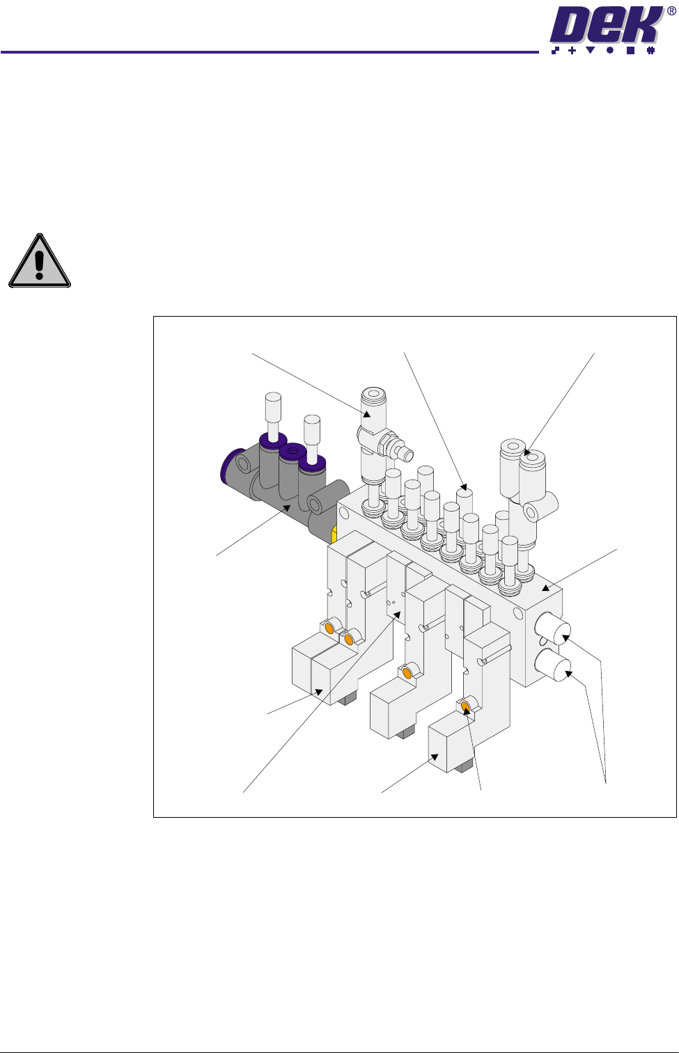
Manifold The manifold distributes the compressed air input directly to the pneumatic
devices, for certain machine options, without passing through a solenoid.
Solenoid Manifold The solenoid manifold distributes the compressed air input to the various
solenoids. Exhaust noise is reduced by two silencers fitted at the end of the
manifold.
WARNING
MANUAL OVERRIDE. MANUAL OPERATION OF PNEUMATIC VALVES MAY
CAUSE A SAFETY HAZARD TO PERSONNEL.
Figure 24-2 Pneumatic Manifold Assembly
In-line Flow Control Valve
Silencers (2 positions)
Manual Override
Plug
Y Union
Blanking Plate
Solenoid Manifold
Manifold
Solenoid Valve 5/2
Solenoid Valve 3/2
31(80$7,&02'8/(
31(80$7,&'(9,&(6
Chapter Issue 3 May 03 Technical Reference Manual 24.5
PNEUMATIC DEVICES
Regulator
Assemblies
There is a minimum of one and a maximum of five regulator assemblies fitted
to the machine as follows:
• Mains Air Input
• Paste Dispenser (option)
• Screen Cleaner Solvent Tank (option)
• ProFlow Software Controlled Air Regulator
• Board Clamps (option)
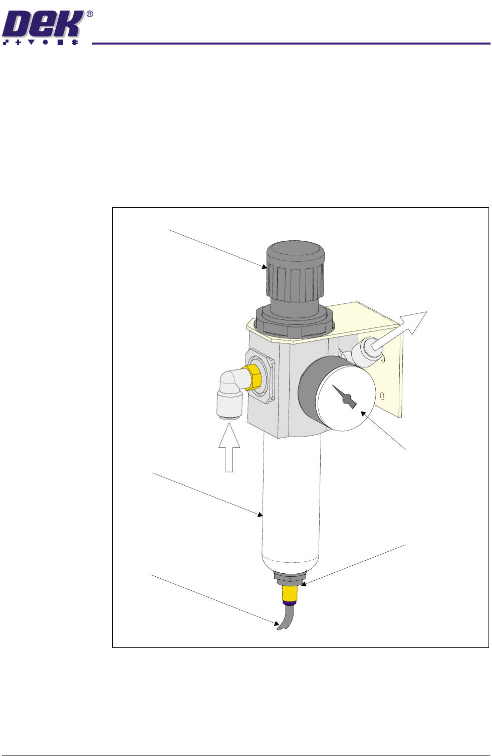
Figure 24-3 Mains Air Regulator Assembly
Filter
Drain
Drain Empty Valve
Pressure Sensor and Gauge
Regulator
Air In
Air Out