Printer 600 Pneumatic Module.pdf - 第14页
31( 80$7,&0 2'8 /( 31(80$7,& '(9,&(6 24.14 Technical Reference Manual Chapter Issue 3 May 03 Pressure Relief Va l v e The pressure rel ief valve i s fitted in p arall el with the screen cl eaner s…
31(80$7,&02'8/(
31(80$7,&'(9,&(6
Chapter Issue 3 May 03 Technical Reference Manual 24.13
In-line Flow
Controller Valve
A flow controller valve (also known as a speed control valve) is connected in-
line with the single line of both the board stop and vacuum tooling. This restricts
the air flow and thus governs the upper speed limit for the pin lift/lower and
board stop lift, or the amount of vacuum for vacuum tooling. Air is throttled when
passing through the valve in one direction, but can flow freely in the other
direction.
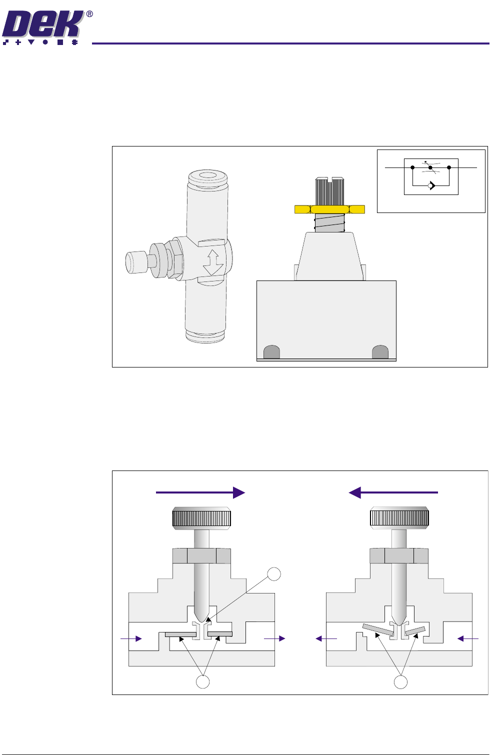
Figure 24-15 In-line Flow Controllers and Symbol
Air entering at Port A is blocked by the check valve (1) and can only flow through
the regulated cross-section (2) before exiting at Port B, therefore controlling or
throttling the speed. Returning air entering at Port B lifts the check valve (3) and
flows freely through to Port A.
Figure 24-16 In-line Flow Controller Cross Section
Symbol
Airflow
Airflow
AABB
1
2
3
31(80$7,&02'8/(
31(80$7,&'(9,&(6
24.14 Technical Reference Manual Chapter Issue 3 May 03
Pressure Relief
Valve
The pressure relief valve is fitted in parallel with the screen cleaner solvent unit
and manually set to either 1 bar (Blue USC) or 0.1 bar (Vortex USC). If the
compressed air supply to the solvent unit exceeds 1 bar, the pressure relief
valve operates venting to atmosphere via a silencer, thus preventing the solvent
unit from becoming over pressurized.
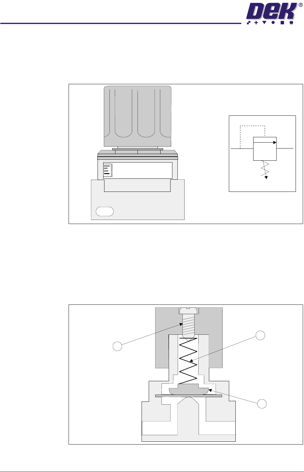
Figure 24-17 Pressure Relief Valve and Symbol
The operating pressure is set by means of compressing/extending a spring (1)
against a diaphragm (2) by adjustment of a set screw (3). The valve is normally
closed, with compressed air at Port A being insufficient to lift the diaphragm (2).
When compressed air above the set level enters the valve, it acts against the
spring pressure lifting the diaphragm and venting through Port B to atmosphere
via a silencer.
Figure 24-18 Pressure Relief Valve Cross Section
Z0
1/4
PRESSURE CONTROL VALVE
MODEL
AP 100
Symbol
Port
A
Port
B
1
2
3
31(80$7,&02'8/(
31(80$7,&'(9,&(6
Chapter Issue 3 May 03 Technical Reference Manual 24.15
Venturi Vacuum
Pump
The pump provides the suction required for vacuum tooling.
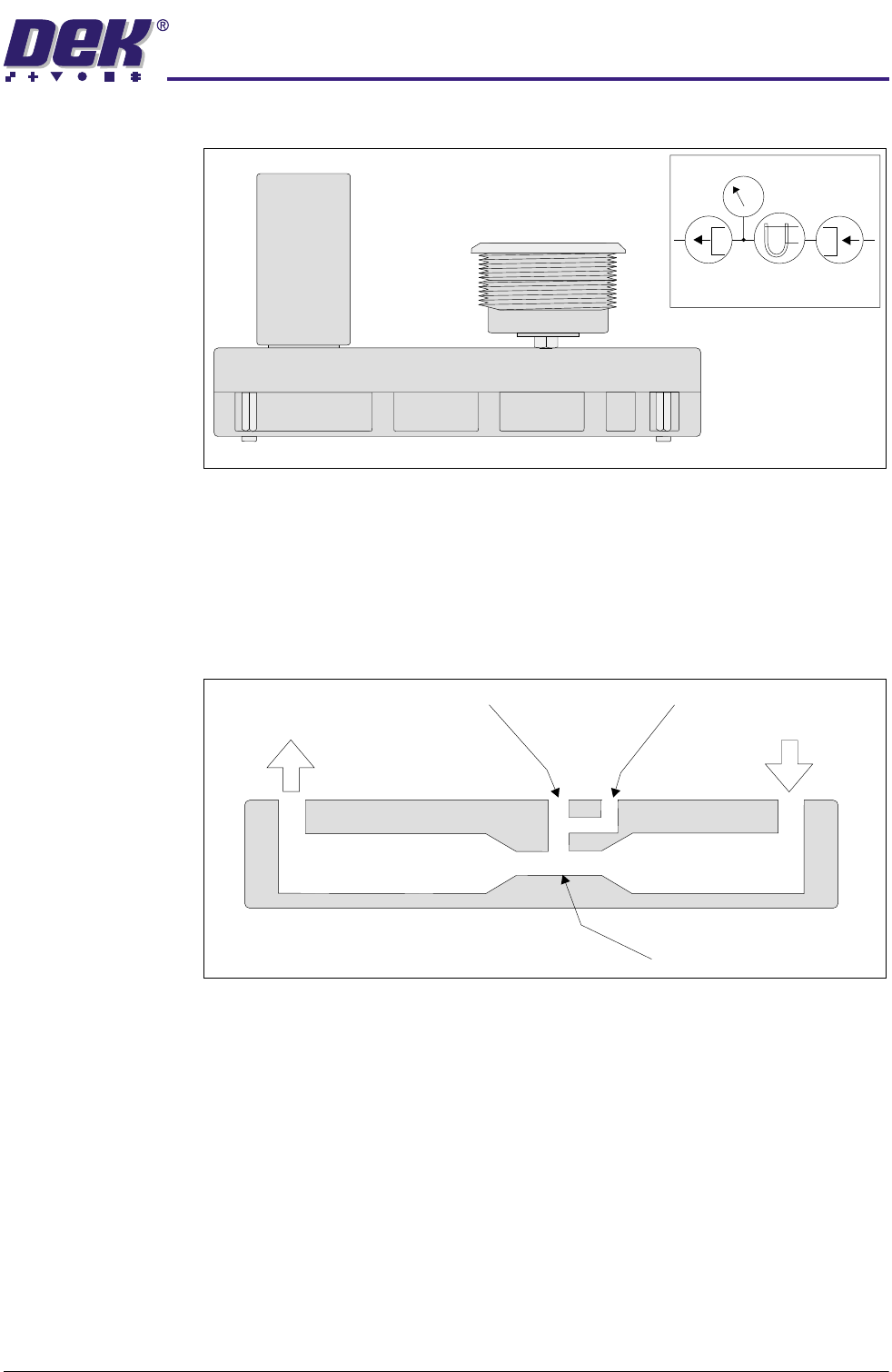
Figure 24-19 Venturi Vacuum Pump and Symbol
The device consists essentially of a convergence in a pipe line, followed by a
short parallel-sided throat and a divergence. Air at the inlet is accelerated
through the throat to the exhaust. The flow of air through the throat causes a
suction at the vacuum port. The faster the flow of air through the throat the
greater the vacuum.
Figure 24-20 Venturi Vacuum Pump Cross Section
Symbol
P
Inlet
Exhaust
Vacuum Gauge
Throat