Nordson-EFD-8040-Operating-Manual.pdf - 第12页
ValveMate 8040 Controller 12 www.nordsonefd.com info@nordsonefd.com +1-401-431-7000 Sales and service of Nordson EFD dispensing systems are available worldwide. Indicator Lamps The indicator lamp at the far left will be …
ValveMate 8040 Controller
11www.nordsonefd.com info@nordsonefd.com +1-401-431-7000 Sales and service of Nordson EFD dispensing systems are available worldwide.
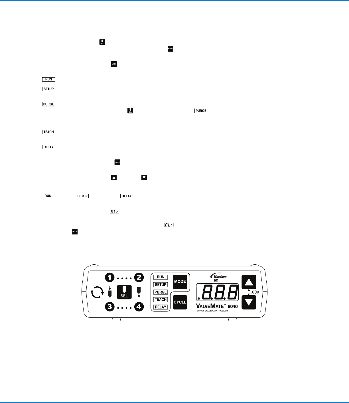
Front Panel Buttons
SEL — Pressing the SEL button scrolls sequentially through ···· and
···· channel time settings appropriate to the MODE selection. Time in
seconds is displayed on the three digit LED display.
MODE — Pressing the MODE
button scrolls through the menu at the left of
the LED. Also used for clearing ALARM faults.
RUN — Enables external initiate inputs. The cycle button is disabled.
SETUP — Setup / testing / and modification of ···· and ····
TIMER modes.
PURGE — Enables individual or simultaneous purge of spray valves.
Used in conjunction with SEL
channel selector, PURGE can
occur with or with out nozzle air function. See page22 for complete
PURGE sequence details.
TEACH — For easy setting / teach of times modes longer spray cycle
applications.
DELAY — Allows user entry to increase or decrease post nozzle air
delay upon completion of spray valve actuation.
CYCLE — Pressing the CYCLE button will provide different results according
to the selected MODE.
TIME SET — Pressing the UP
or DOWN buttons will change valve-on time
for the selected valve(s) or the DELAY time. Pressing both buttons
simultaneously will zero out the time. These buttons are enabled in the RUN
, SETUP , and DELAY modes only.
ALARM INDICATORS — At the beginning of any of the spray activities, if
ALARM circuit is open, “ALr”
flashes on the LED display. ALARM condition
needs to be corrected — either low pressure, low level, or other alarm open
circuit. After the circuit is restored, the flashing “ALr”
becomes steady.
Press MODE button to resume normal operation.
Operating Features
ValveMate 8040 Controller
12 www.nordsonefd.com info@nordsonefd.com +1-401-431-7000 Sales and service of Nordson EFD dispensing systems are available worldwide.
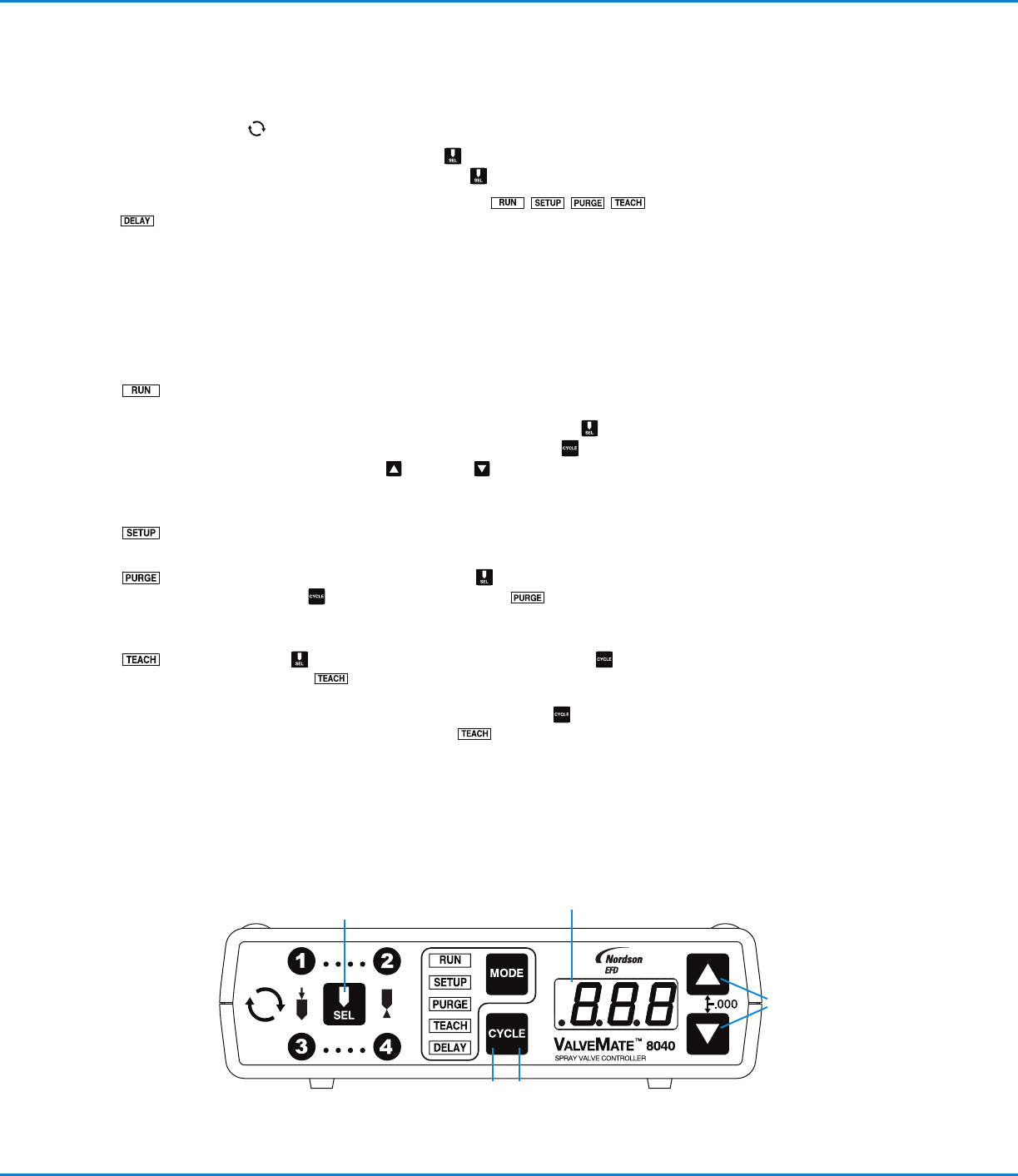
Indicator Lamps
The indicator lamp at the far left will be lit any time valves are actuated.
The four numbered spray lamps around the SEL button will be lit ···· and
···· sequentially then all ON by pressing the SEL button.
In the center of the front panel are five indicator lamps:
. These lamps indicate the mode of operation.
Modes of Operation
RUN — The ValveMate 8040 is ready to be initiated through the I/O,
resulting in a spray cycle. Time settings can be made “on the fly” while
the machine is running. For “on the fly” adjustment,
select
appropriate channel, ···· and ····. Press CYCLE . LED
display will “flash.” Press UP or DOWN arrow to add or subtract
time to selected channel. When finished, press CYCLE to lock in new
TIME. Initiate signals are only enabled in the RUN mode.
SETUP — In the SETUP mode, time settings can be changed and spray
volume tested.
PURGE — This allows purging from selected or all channels for the
duration the CYCLE button is pressed. PURGE can occur with
or without nozzle air function. See page22 for complete PURGE
sequence details.
TEACH — Select channel. Pressing and holding the CYCLE
button in the TEACH mode will begin “flashing” of the LED display
for 5 seconds before TEACH function begins. Add incremental time to
selected channel by continued press and hold of CYCLE button, or
“.000” out channel time and begin TEACH sequence described
above. Repeat sequence for each channel.
FLASHING LED
Operating Features (continued)
ValveMate 8040 Controller
13www.nordsonefd.com info@nordsonefd.com +1-401-431-7000 Sales and service of Nordson EFD dispensing systems are available worldwide.
Modes of Operation (continued)
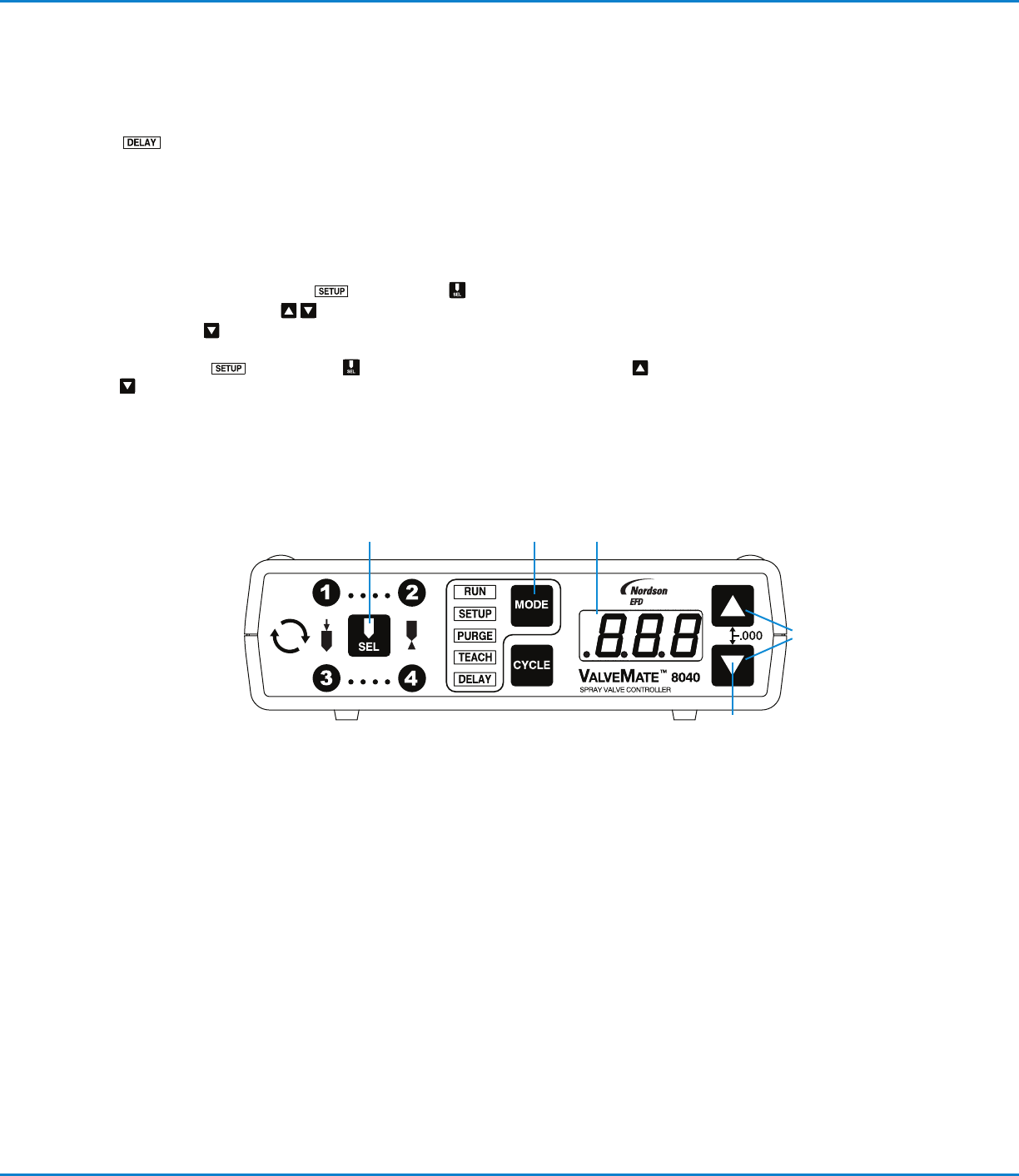
DELAY — In the DELAY mode, the time set buttons can be used to
enter a post nozzle air delay for the selected spray valve. This delay is
used to ensure that all fluid is atomized after the valve closes leaving a
clean nozzle.
Steady Mode Operation
Channel ···· and ···· can be put into a steady mode / time override
operation.
In Setup mode , press SEL for selected channel.
Press both UP / DOWN
buttons to “.000” out channel time. Press and
hold DOWN
button for 5 seconds or until “– – –” appears on LED display.
Repeat steps for each channel requiring steady mode. To return to TIME setting,
enter SETUP mode. Select appropriate channel. Press UP / DOWN
buttons simultaneously. “.000” will appear on LED display. Re-enter time
value as needed.
Operating Features (continued)