Nordson-EFD-8040-Operating-Manual.pdf - 第15页
ValveMate 8040 Controller 15 www.nordsonefd.com info@nordsonefd.com +1-401-431-7000 Sales and service of Nordson EFD dispensing systems are available worldwide. Connecting Power Connect the power cord (ordered separately…
ValveMate 8040 Controller
14 www.nordsonefd.com info@nordsonefd.com +1-401-431-7000 Sales and service of Nordson EFD dispensing systems are available worldwide.
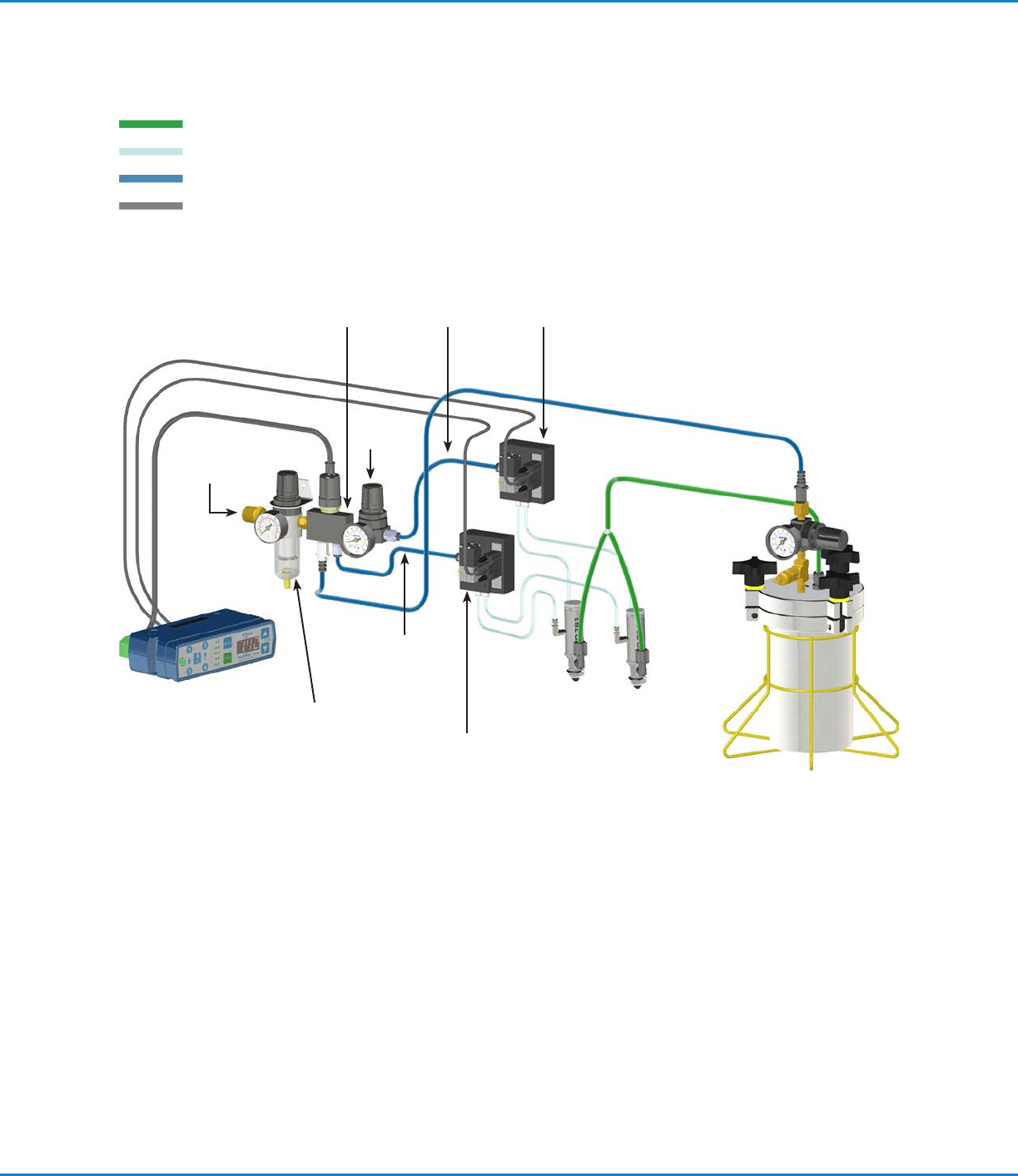
Typical Setup — Two Valve System Installation
Alarm
In
Low pressure
switch
Tank air
line
Fluid feed
line
Actuating
air
Spray valves
1-Liter tank
Filter
regulator
Solenoid cables
Nozzle air
solenoid
ValveMate 8040
Controller
Regulated air
supply
Nozzle air
regulator
Actuating air
solenoid
Nozzle air
supply
Actuating air
supply
Nozzle
air
Fluid
Actuating air, nozzle air
Constant air
Electrical
ValveMate 8040 Controller
15www.nordsonefd.com info@nordsonefd.com +1-401-431-7000 Sales and service of Nordson EFD dispensing systems are available worldwide.
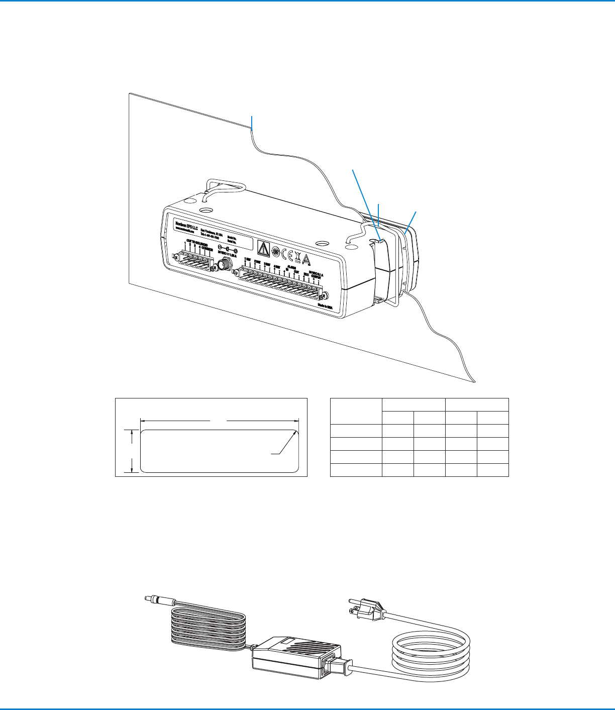
Connecting Power
Connect the power cord (ordered separately) to the appropriate input voltage.
Mounting the ValveMate 8040
The ValveMate 8040 can be mounted either over or under a cabinet using screws.
Panel mount
bezel
Fits M4 or UNC / UNF #8
screws for under or over
cabinet mounting
Panel thickness
(see table)
Spring
clamps
Dimension
Min Max
mm in. mm in.
A 183.6 7.23 185.2 7.29
B 51.6 2.03 53.1 2.09
C R3.3 R.13 R9.4 R.37
Thickness 1.6 0.063 2.3 0.091
B
A
C (4X)
Panel Cutout Dimensions
ValveMate 8040 Controller
16 www.nordsonefd.com info@nordsonefd.com +1-401-431-7000 Sales and service of Nordson EFD dispensing systems are available worldwide.
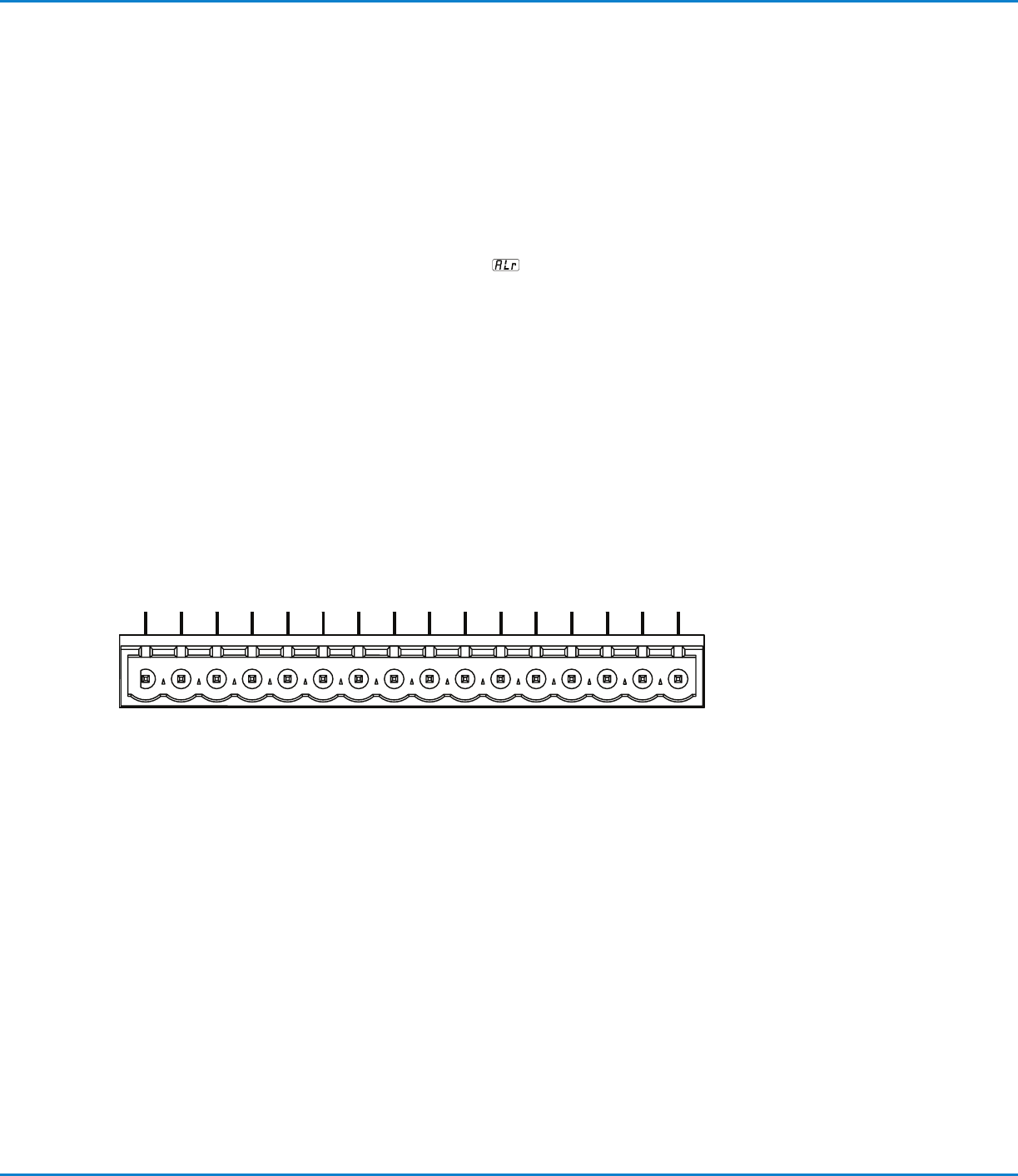
The 16 pin terminal strip includes four dispense valve initiate inputs, an alarm
I/O, an End of Cycle output, and a 24VDC courtesy power output.
The four initiate inputs can be connected in series, parallel, or to separate input
sources for independent valve control, or ability to disable a specific valve when
using “part in place” verification.
For a detailed connection schematic and instructions, refer to page17.
The alarm I/O is used to monitor air supply pressure and / or tank low level. This
I/O can be used to operate an audible alarm, or be connected to the machine
controls to shut off the machine if air pressure or tank level is low. In addition,
when the alarm is activated, the display will flash “ALr”
, indicating that air
pressure or tank level has dropped below minimum.
The End Of Cycle (EOC) feedback can send a signal back to the machine
controls, signaling when the dispense cycle is finished. Using this signal can
increase machine productivity by eliminating any delay after the dispense cycle
and also confirms a dispense cycle has occurred. 2 INIT and 4 INIT are non-
active inputs. As long as an initiate sequence is in progress on any channel, the
EOC circuit is open. Maximum load is 100 mA from 5 to 24 VDC.
Input / Output Connections
--------
ALARM
1 INIT.2 INIT.3 INIT.4 INIT. IN OUT EOC
OUTPUT
++++++++
24 VDC 0.1A
ALARM 24 VDC 0.1 A
1 INIT. 3 INIT. IN EOC2 INIT. 4 INIT. OUT OUTPUT