Nordson-EFD-8040-Operating-Manual.pdf - 第19页
ValveMate 8040 Controller 19 www.nordsonefd.com info@nordsonefd.com +1-401-431-7000 Sales and service of Nordson EFD dispensing systems are available worldwide. Initiate Connection Schematic 3 WA Y , 2 POSITION 2 SOLENOI…

ValveMate 8040 Controller
18 www.nordsonefd.com info@nordsonefd.com +1-401-431-7000 Sales and service of Nordson EFD dispensing systems are available worldwide.
Initiate Connection (continued)
End of Cycle Connection (EOC)
Upon completion of a spray cycle, an open collector circuit closes and remains
closed until the next spray cycle. This circuit can be utilized to signal back to a
host computer, start another device in sequence or other operations that need
to be tied into the completion of the spray cycle. This circuit will close when all
spray activity has completed.
Upon closure, power from an external source is allowed to pass through the
circuit to operate a 5 to 24 VDC load or be monitored by the host machine
controls.
The load illustrated is a relay, but this could be any device that will operate
within the 5 to 24 volt range. Power consumption of the load must not exceed
250 mA.
24 VDC Output
Courtesy 24 volt DC 100 mA (maximum) can be used to provide power to EOC
and ALARM out circuits for signaling purposes. Also, can be used as a power
source for an indicator device or initiate signal through a contact closure switch
to the 4-channel Initiate circuit.
ValveMate 8040 Controller
19www.nordsonefd.com info@nordsonefd.com +1-401-431-7000 Sales and service of Nordson EFD dispensing systems are available worldwide.
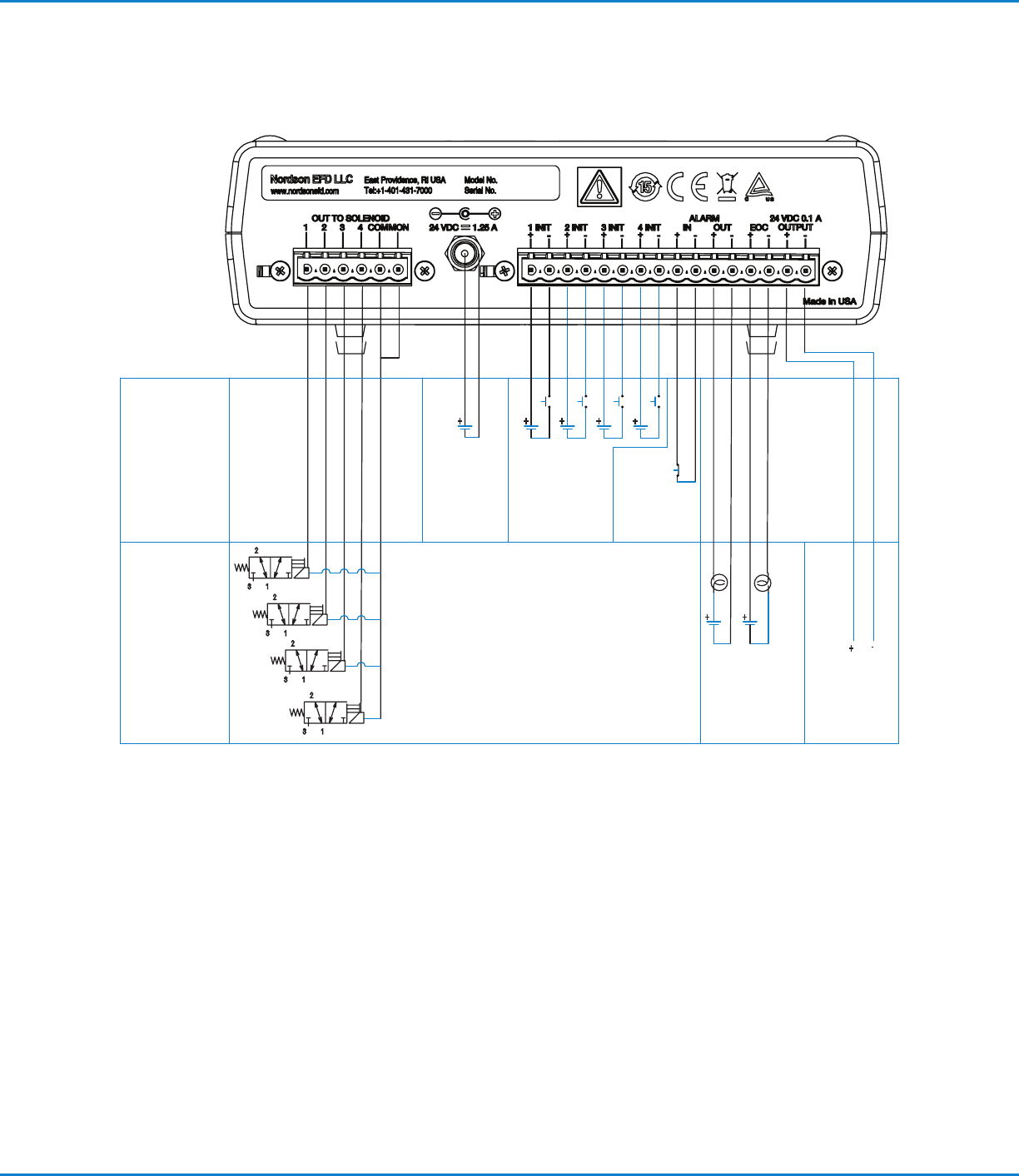
Initiate Connection Schematic
3 WAY, 2 POSITION
2 SOLENOID VALVES
24 VDC
5 W MAXIMUM, EACH
NEG. COMMON
SWITCH CLOSURES
5–24 VDC SOURCE
100 mA MAX.
COURTESY
SUPPLY 24 VDC
100 mA MAX.
VOLTAGE INITIATE
5–24 VDC
2.2 mA AT 5 VDC
15 mA AT 24 VDC
ALARM IN
NC SWITCH
10 mA MAX.
INPUTS
OUTPUTS
POWER IN
24 VDC
1.25 A MIN.
ValveMate 8040 Controller
20 www.nordsonefd.com info@nordsonefd.com +1-401-431-7000 Sales and service of Nordson EFD dispensing systems are available worldwide.
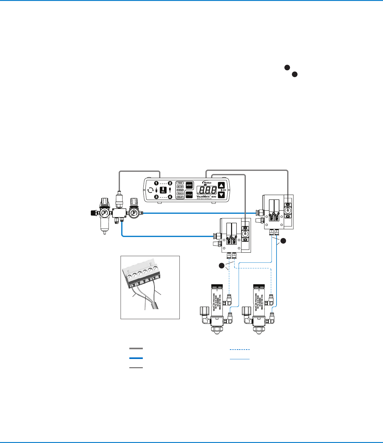
Mount the solenoid packs in a convenient location
near the spray valve station.
Interconnect the solenoid pack to the ValveMate
8040 controller using the cable supplied.
Refer to the inset for color coded wire designation
Connect a regulated and filtered air supply to the
solenoid pack.
Supply pressure to the solenoids should be set to
5.5bar (80psi).
Install the Dispense Valves
All EFD spray valves are supplied with an installation
manual. The manual will explain the operation of the
spray valve and also how to set up the valve with the
fluid reservoir.
Connect the valve actuating air hoses
to the appropriate solenoid output.
6a
White hoses to
white push-in fittings for actuating air.
6b
Black hoses to
black push-in fittings for nozzle air.
Installing the Air Solenoids
Electrical
Constant Air
Fluid
Actuating Air
Nozzle Air
Common
— Blue
Channel 2 — Brown
Channel1
— Black
6a
6b