Nordson-EFD-8040-Operating-Manual.pdf - 第23页
ValveMate 8040 Controller 23 www.nordsonefd.com info@nordsonefd.com +1-401-431-7000 Sales and service of Nordson EFD dispensing systems are available worldwide. Part Numbers NOTES: • Power cords are ordered separately. •…

ValveMate 8040 Controller
22 www.nordsonefd.com info@nordsonefd.com +1-401-431-7000 Sales and service of Nordson EFD dispensing systems are available worldwide.
Set tank pressure. For low viscosity, low pressures and
high viscosity, higher pressure.
Using the MODE button on the ValveMate controller,
place the controller in the PURGE mode. In
PURGE mode only, channels ···· and ····
can be selected independently without nozzle air
pressure.
Using the SEL button, press to sequence as follows:
Place a container under the spray valve and press the
CYCLE button to open the spray valve and flow
material until all air is purged from the system. Adjust
the tank pressure, or valve stroke knob to set a flow
rate that is not too low or too high. A goal starting point
for a fine spray is one drop of fluid per second. For
heavier spray, increase the drop rate just below where
the flow becomes a steady stream. Adjust flow using a
combination of tank pressure and valve needle stroke.
Testing the Spray Valves
Set nozzle air pressure regulator to 0.7bar (10psi).
Using the PURGE mode again, actuate the spray
valves and observe the spray sequence: ····
····
Press SEL: Channel only is active is off.
Press SEL: Channels
···· only are active.
Press SEL: Channel
only is active is off.
Press SEL: Channels
···· only are active.
Press SEL: Channels
and only.
Press SEL: All channels are now active.
Press mode and place controller in SETUP mode.
Using the UP / DOWN buttons, set a spray time
of 0.05 seconds for all valves.
Press the CYCLE button to initiate a spray cycle.
Increase or decrease the time or tank pressure to arrive
at the desired deposit size. The primary control of
deposit size is the valve open time. Final time setting
may be different for each valve as this is the way we
compensate for minor variations in tubing length or
tolerance stack up.
The system is now ready to be initiated by the machine
controls when the machine is started.
ValveMate 8040 Controller
23www.nordsonefd.com info@nordsonefd.com +1-401-431-7000 Sales and service of Nordson EFD dispensing systems are available worldwide.
Part Numbers
NOTES:
• Power cords are ordered separately.
• Solenoids are ordered separately based on the number of valves in the system. Each solenoid kit includes the
prewired 6-pin connector and housing, a 3.6 m (12 ft) cable cordset, an input air hose, and push-in fittings.
Part # Description
7022120 8040 spray valve controller
7014871 Kit, power cord, American plug
7014872 Kit, power cord, European plug
7022250 Solenoid valve kit, two in-line solenoids for nozzle / actuating air
7022251 Solenoid valve kit, two dual blocks for nozzle / actuating air
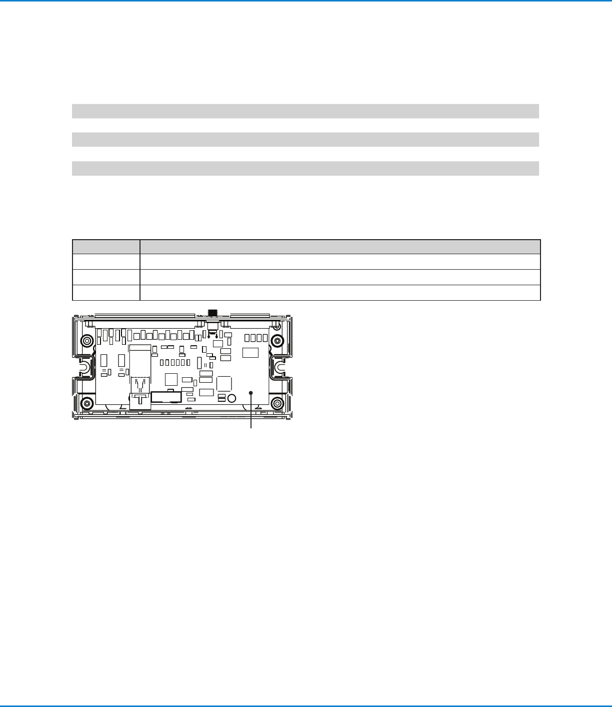
Replacement Parts
Part # Description
7002002 5-micron filter / regulator
7022055 Main PC board, VM8040
7026543 Kit, DC cable assembly, 2 m (6.6 ft) locking connector
7022055
ValveMate 8040 Controller
24 www.nordsonefd.com info@nordsonefd.com +1-401-431-7000 Sales and service of Nordson EFD dispensing systems are available worldwide.
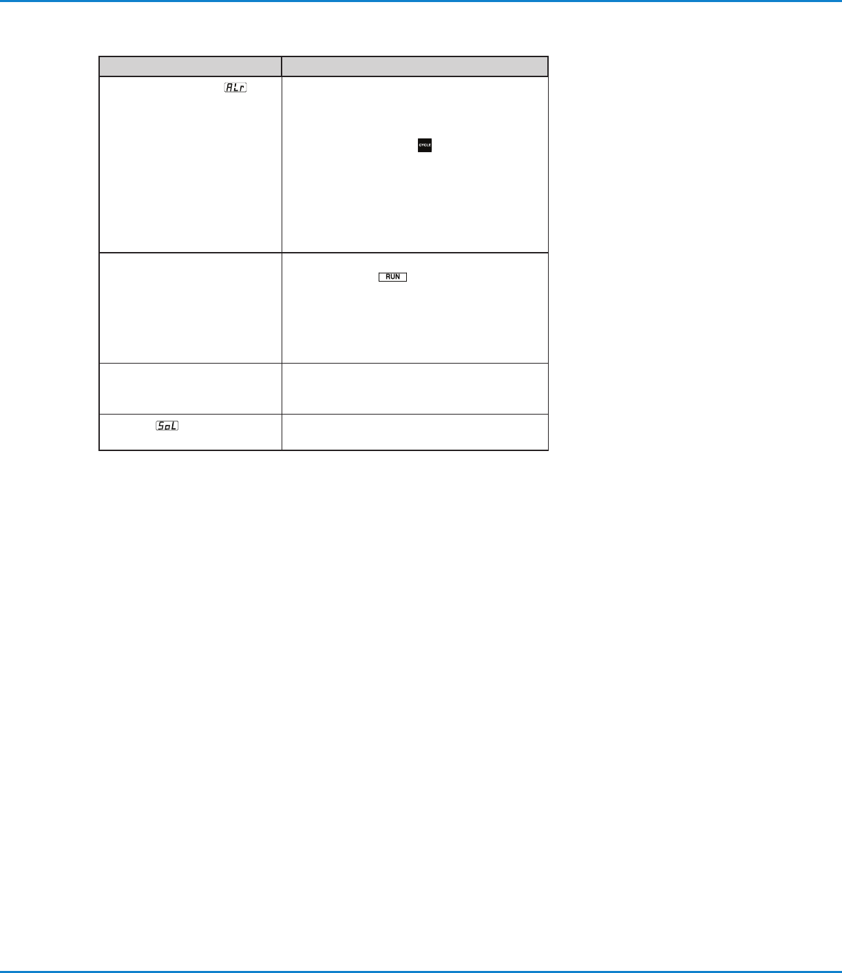
Troubleshooting
Problem Possible Cause and Correction
LED is blinking “ALr”
and
will not accept initiate signal.
Air pressure to the solenoid pack has
dropped below 4.1bar (60psi) or if low level
float switch is used, tank level is low. Raise
the input pressure to 4.8bar (70psi) or refill
the tank. Press CYCLE
button to reset.
If problem persists, make sure devices such
as air cylinders are not causing a pressure
drop in the ValveMate 8040 solenoid pack
input air line. If no ALARM switch is being
used, the ALARM IN + / - terminals must have
a jumper installed to disable ALARM feature.
Unit is not responding to the
initiate signal.
Check to make sure the unit is not in a mode
other than RUN
. Response delay in
pneumatic circuit does not allow the valve to
open when time is set at or below 0.010
seconds. Increase time. Initiate signal may
have a low level of leakage. The signal must
break clean before the next signal is initiated.
Timer is inoperative. Check to make sure the unit is not in the
steady mode. The timer is very reliable. Any
failure is total so no inconsistency is possible.
Flashing
on LED display.
Short on the OUT TO SOLENOID circuit.
Check solenoid wiring connections.