M20_Ope_E.pdf - 第191页
Chapter 5 Libraries 5-41 Camera Distance from camera Thickness Comp Pickup Surface Hei g ht Z offset for vision process Thickness Camera Distance from camera Comp Pickup Surface Height 5-1-3-4 Advanced Settings Menu: Com…

Chapter 5 Libraries
5-40
Polarity: Specify the polarity of the component (Non-polarized/ Polarized/
Polarized(no-prerotation) ).
When the component is polarized and yet you don’t want to
pre-rotate the component, select “Polarized(no-prerotation)”.
When the component is polarized (with prerotation), the
component is first pre-rotated to the placement angle and then
vision processed. This process is suited for the components, which
require special accuracy.
ST-R: When the component set on the rear station is polarized or
polarized (with prerotation), the component package-angle is
automatically recognized at 180 degree rotated.
Pre-rotation is not available in the following case:
When the component is 5mm square or smaller and is processed by the scan
camera using the process mode of either [Chip], [Transistor], [Terminat.],
[Blob], or [CPL].
In this case, disable the use of pre-rotation. See Note in Chapter 9, User
Parameter, Functions.
Note: On the M6, “Polarized” (with prerotation) is automatically selected
for all components automatically.
Simlt. Pickup Perm.: Simultaneous pickup permission.
* Increment : 0.01mm
See Multiple/Simultaneous Pickup in Chapter 2.
Thickness: Component thickness
* Increment : 0.01mm
Size X/Y Enter the component’s X-directional size (width) and Y-directional
size (length). This data will be referred to when the graphic view
function of our offline software iOSII is used. (These parameters can
be left empty when performing production.)
Vision Process Result: By setting [Vision Process Result] setting to “Disabled”, you can
place the component disregarding the result of the vision
processing. In this case, the component positional offset won’t be
compensated. By default, “Enabled” is entered so the result of the
vision processing is applied.
Placement in Scan Process: Specify whether to perform placement while the scan camera is
moving. This allows the head to start placement before the scan
camera finishes scanning. To use this function, specify “Enabled” in
the cell.
Optimization Priority: Specify the placement order of each component by setting
“Optimization Priority” for each component code. The allowable
numbers are 0 to 99. When there is no need to set priority, set “0”.
Chapter 5 Libraries
5-41
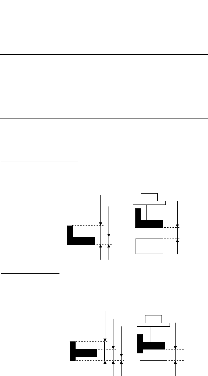
Camera
Distance from camera
Thickness
Comp Pickup Surface Hei
g
ht
Z offset for vision process
Thickness
Camera
Distance from camera
Comp Pickup Surface Height
5-1-3-4 Advanced Settings
Menu: Component Library>Tool>AdvancedSetting
You can define miscellaneous settings related to the pickup, placement, and vision process of
the component. Usually default settings will do. But when there is a need to change the setting,
click the line of the component and select this menu.
Window:
Retry:
Vision Process Retry: The number of retries if vision process error occurs.
Select a value from 0 to 9.
Pickup Retry: The number of retries if pick up error occurs.
Select a value from 0 to 9.
Choke/Feeder Retry: The number of retries if nozzle clogging or feeder trouble occurs.
Select a value from 0 to 9.
Vision Process Time:
This setting is used for the calculation of Simple Placement Optimization, The parameter
cannot be edited.
Detailed Thickness:
Component Pickup Surface Height:
Specify the length from the bottom to the pickup surface. No need to specify when it is the
same as the component thickness.
Z offset for vision process:
Specify the offset value for vision process if the target surface for vision process is not at the
bottom of the component.
Chapter 5 Libraries
5-42
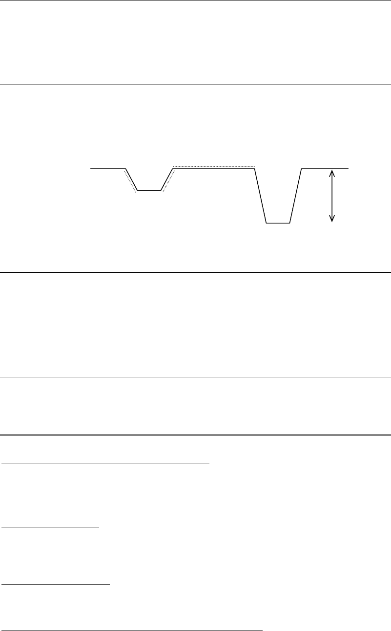
Placement Speed (XY、Z、θ)
Placement speed 1 (minimum speed) to 100 (maximum speed) (Unit: %)
See the chart below.
Placement acceleration 1 (minimum speed) to 100 (maximum speed) (Unit: %)
Pickup Speed (Z)
Pickup speed 1 (minimum speed) to 100 (maximum speed) (Unit: %)
See the chart below.
Pickup acceleration 1 (minimum speed) to 100 (maximum speed) (Unit: %)
Placement Timing
Head suction off ← Head down complete at PCB (Positive Value: OFF before, Negative Value:
Off after)
Vacuum Brkr on command at PCB → Vacuum Brkr off command
X,Y-axis motors stop at PCB → Head down command
Head down complete signal at PCB → Head up command
Pickup timing
Head down complete signal at feeder → Head up command
X,Y-axis motors stop at feeder → Head down command
Others
Vacuum Check > Enter pickup threshold [mmHg]
If you want to set the pickup vacuum threshold value for each component, make setting for this
item. (Unit: mmHg) The default is “0”. (If “0” is set, the pickup vacuum threshold value for the
nozzle that picks up this component will be used.)
Default > Feeder/Pallet
If the feeder/pallet to be used for this component has been specified, it will be entered in
[Feeder/Pallet] automatically when the component code is entered in the pickup data or when
<Copy Code> button is clicked.
Default > Packaging/Tray
If the component feeder/tray to be used for this component has been specified, it will be
entered in [Packaging/Tray] automatically when pickup data is created.
Component Remain Count Management > Initial Supply Count
Enter an initial supply count value for this component. (Unit: pcs.)
Normally, enter the number of components in the packaging state directly.
See Chapter 9_ Running a job > ● Component Remain Count Management> Advanced Setting
for Component Library
Pl
ace
m
e
n
t
speed
Pickup point
Pl
ace
m
e
n
t
po
in
t
Pickup speed
Z