M20_Ope_E.pdf - 第511页
Chapter 17 Multi Conveyor 17-1 Chapter 17 Multi Conveyor Multi Conveyor Outline Pa rameter Setti ngs PCB Data Manual Op erat ion
Chapter 16 Dispenser
16-40
- - - Blank P
a
ge - - -
Chapter 17 Multi Conveyor
17-1
Chapter 17
Multi Conveyor
Multi Conveyor Outline
Pa
rameter Setti
ngs
PCB Data
Manual Op
erat
ion
Chapter 17 Multi Conveyor
17-2
Multi Conveyor Outline
The “Multi Conveyor” detects the transferred board by the laser sensor fixed on the head assembly.
There are no board arrival sensor and board stopper that a conventional conveyor system has.
The “Multi Conveyor” provides following features.
1. Entrance and/or Exit buffer conveyors are automatically chosen and work depending on the
board length. (“Entrance” or “Exit” must be selected to be used as a buffer conveyor for machines
M10 and D10.)
2. The position in conveyor width direction to detect the board by the laser sensor can be
programmed for a board with “Cutout”.
3. The board is clamped in the best position on the conveyor where close to the fixed camera for
saving the running time.
4. The board flow direction can be changed in the system parameter easily.
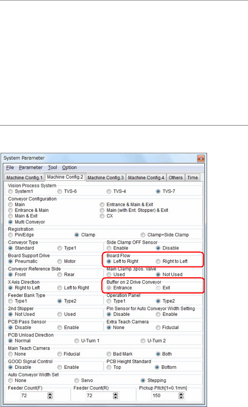
Parameter settings
Set the parameters for using multi conveyor.
【Menu】 System > System Parameter > Machine Config. 2