M20_Ope_E.pdf - 第75页
Chapter 2 Creating and Editing a Program 2-31 2-7 Creating Program and Pickup Data 2-7-1 Creating a Program Menu: Program Create component placement data and fi ducial/bad mark data in a program. Program> View(Simple/…
Chapter 2 Creating and Editing a Program
2-30
If the exit conveyor is not installed (exit buffer is not available), the PCB unloading completion
check with the exit sensor is not performed. Therefore, if this time setting is improper, a
component-mounted PCB may not be unloaded completely. So, take great care to make each time
setting.
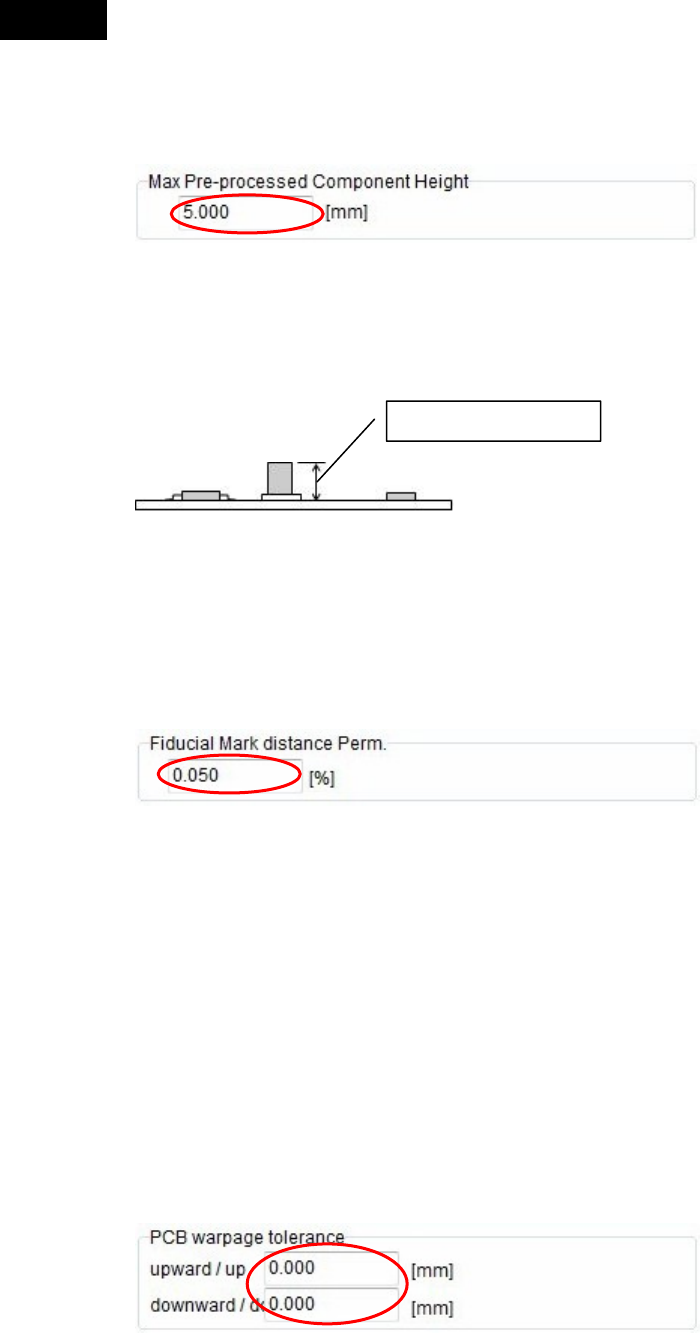
Max Pre-processed Component Height (Head travel height)
Enter the maximum component height already placed in the previous process.
First, the head travels over the PCB based on the setting, and then the head travel height is
adjusted based on the placed component height levels.
If there is no pre-processed component on the board, set “0.00”.
Fiducial Mark Distance Perm.
When the fiducial mark on the PCB is detected during production, the distance between the marks
is judged based on the distance between the marks of the fiducial mark coordinates set in the
program.
According to the results of this judgement, extended or contracted PCB or warped PCB can be
rejected without production.
Enter a permissible value (±%) in response to the reference distance value between the marks.
If the distance between the marks that have been detected exceeds this permissible value, relevant
error is given.
PCB warpage tolerance
Enter upward and downward PCB warpage tolerance values.
Tolerance values you can enter are 0 to 4.0 mm for the upward warpage tolerance and 0 to 1.0 mm
for the downward tolerance.
The force control is used in a range of “upward tolerance value + downward tolerance value” to
place components.
In particular, as you enter the downward warpage tolerance value, the placement height is made
low to take corrective actions against the PCB downward warpage.
Note: Basically, it is recommended to correct the PCB downward warpage using the push-up pin.
Caution
Max component height
Chapter 2 Creating and Editing a Program
2-31
2-7 Creating Program and Pickup Data
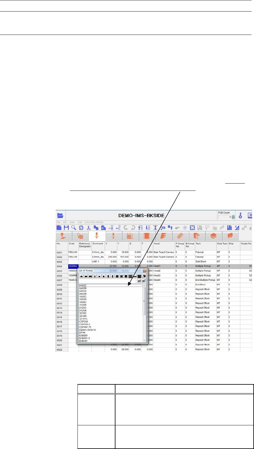
2-7-1 Creating a Program
Menu: Program
Create component placement data and fiducial/bad mark data in a program.
Program> View(Simple/Detail)
You can either show or hide the columns of [Reference Designator], [Comment], and [Type] by
selecting View(Simple/Detail).
Window:
No.: The order the program is executed.
* Up to 10000 steps per program
Code: Identification code for components and marks. It allows the operator to
tell what a step is for, a placement step or fiducial/bad mark step. Code
serves to link Placement & Mark Data, Pickup Data, and libraries with
each other, therefore a code is required for each step. To enter a code to
[Code] field, right-click the mouse with [Code] field selected and select
a code from the provided list, or type in a code. By selecting
component-type icon, you can extract the selected type of component
codes only in the list. There are two kinds of codes available,
component code and mark code. Right-click a desired cell to select a
code through the filtering by the component type or enter a code
directly through the keyboard.
* Up to 38 characters can be entered.
Note: To display the list of fiducial codes by right-clicking the mouse, enter “Fiducial” to [Task] field in
advance. To display the list of bad mark codes, enter “Bad Mark Positive Logic” or “Bad Mark
Negative Logic” to [Task] field in advance.
Code Links “Placement & Mark Data” To...
Component
code
* Pickup data—Component pickup coordinates and
others.
* Component library—Component characteristics
and size data.
Mark code
* Fiducial data
* Bad mark data
Used for mark sensing with the main teach camera.
Chapter 2 Creating and Editing a Program
2-32
Reference Designator: Alphanumerals printed on a board used for identifying placed
components.
* Up to 14 characters can be entered.
Comment: Any annotation for the component. Used for user identification.
* Up to 40 characters can be entered.
X, Y, Z, T: Placement/mark coordinates. To perform teach entry for the current
step, click the right mouse button or click Tool>Teach.
* Increment—X/Y/Z : 0.01mm, T : 0.01deg.
T: Counter-clockwise in the downward-looking perspective indicates
positive T.
-
+
Plus sign (+) is not needed for positive values. Minus sign (-) can be
entered from the keyboard.
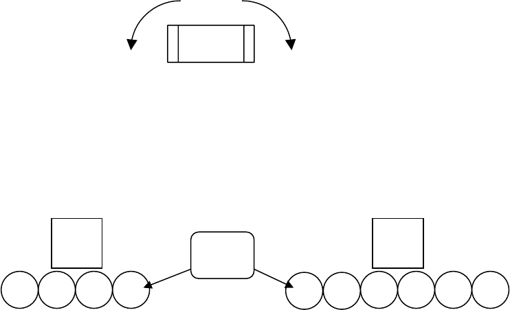
Head: Click the right mouse button and select a head from the given list. The
head assembly is configured as follows.
F Group No.: Specify the fiducial number.
0 : Global fiducial(default):
1-249 : Local fiducial
At a fiducial step, enter a number (0-249) you want to assign to the
fiducial step. At a placement step, enter the fiducial number assigned
to the fiducial step you want to use for the placement.
B Group No.: Click the right mouse button and select bad mark number.
0 : Standard bad mark
1-249 : Group bad mark
255 : Master bad mark
254 : Master bad mark (excluding group bad mark processes)
At a bad mark step, enter a number you want to assign to the bad mark
step. At a placement step, enter the bad mark number assigned to the
bad mark step you want to use for the placement.
Task: Click the right mouse button and select a task for the step. (See later in
this chapter for detailed description.)
● Start Block Placement: Flags the start of a program block in a repeat program. Repeat
programs are typically used for multi-up panels. Actual program
begins at the next step.
● End Block Placement: Flags the end of a program block in a repeat program. Repeat
programs are typically used for multi-up panels. Actual program ends
at the previous step.
● Repeat Offset: Indicates the program repetition occurs at this step. Consists only of
offset values. Repeat program is typically used for multi-up panels.
1
2 3 4
Main
teach
camera
4 heads s
p
ecs
(
To
p
view
)
1
2
3 4
5
6
6 heads s
p
ecs
(
To
p
view
)
Head
Nos.
Main
teach
camera