M20_Ope_E.pdf - 第91页
Chapter 2 Creating and Editing a Program 2-47 2-7-1-6 Fiducial Function Menu: Program>Placement&Mark Data>Task>Fiducial Program>Placement&Mark Data>Task>Fiducial By using recognition results of …
Chapter 2 Creating and Editing a Program
2-46
Note: When using the PCB select master bad mark function, the following must be observed.
① In principle, the “Preliminary Fiducial Process” and “Preliminary Bad Mark Process” user
parameters must be set to “Disable”. If they are set to “Enable”, the tact time will lengthen
since all the fiducial and bad marks on the program are processed first.
② Two or more PCB types of program data are defined in the program, but they are handled as
one type at program management.
③ The PCB select bad mark must be set using the mark coordinates by which only the target
PCB can be identified.
Note: As the example given in “PCB Select Bad mark Setting Method” in the previous page, in order to
identify more than three PCB types, the PCB select bad mark positions must differ from each other.
However, when identifying only two PCB types, the same coordinates can be used for the PCB
select bad marks by setting the positive/negative logic of the bad mark function as shown above.
In this case, recognition of the bad marks is performed only once, resulting in shorter tact time.
④ To use PCB select bad marks, block data conversion must have been performed on the
placement program for each PCB. If a repeat block is defined for each PCB type, the program
must be converted using the block data conversion function.
⑤ If any of the placement programs are not selected, a “#1548 No PCB has been selected in the
PCB select bad mark" process."” error will occur and the mounter stops. In this case, cancel
production and remove the board.
Note: Block Data Conversion Function
Data Edit Utilities> Block Data Conversion
Data for board 2
PCB select
master bad mark
for board 2
Data for board 1
PCB select
master bad mark
for board 1
Chapter 2 Creating and Editing a Program
2-47
2-7-1-6 Fiducial Function
Menu: Program>Placement&Mark Data>Task>Fiducial
Program>Placement&Mark Data>Task>Fiducial
By using recognition results of the fiducials provided on a PCB, the fiducial function corrects the
PCB positioning error resulting from errors in machining the PCB contour and locate pin holes,
PCB claming mechanism fluctuations and local distortion or warps on the PCB.
There are one-point, two-point, or four-point fiducial functions. Two or four fiducials are used as a
set, but it is okay if each mark is different in shape.
Type Target correction Remark
One-point fiducial
X, Y
Two-point fiducial
X, Y, θ
When “Without stretch/shrink correction” is
selected
X, Y, θ, Stretch/shrink
correction
F group “0” only / All fiducial marks (select)
Four-point fiducial
X, Y, θ, Deform correction
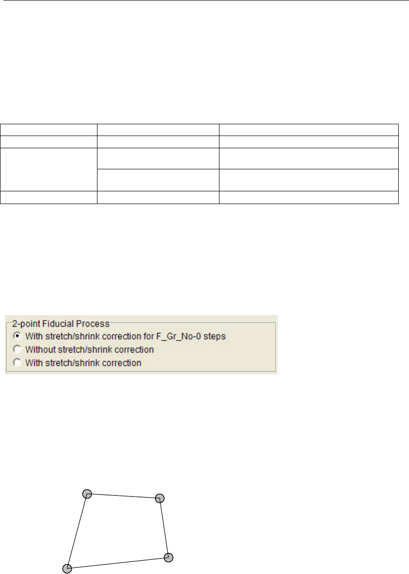
Note: In the case of two-point fiducial, it is possible to select whether stretch/shrink correction is to be
performed.
To use stretch/shrink correction, it is necessary to select whether correction is to be performed for
the global fiducial (F group “0”) only or all the fiducial marks including local fiducial marks.
Menu: Program>Board Data
Note: Stretch/shrink correction will be performed when a shared fiducial mark(F Group No. 255) is
specified.
Note: In case of the 4-point fiducial, the four marks must be positioned so that they make a square shape.
The lines AB and CD (or BC and DA) need not be parallel to each other. Each internal angle must
be smaller than 180 degrees.
A
B
C
D
Chapter 2 Creating and Editing a Program
2-48
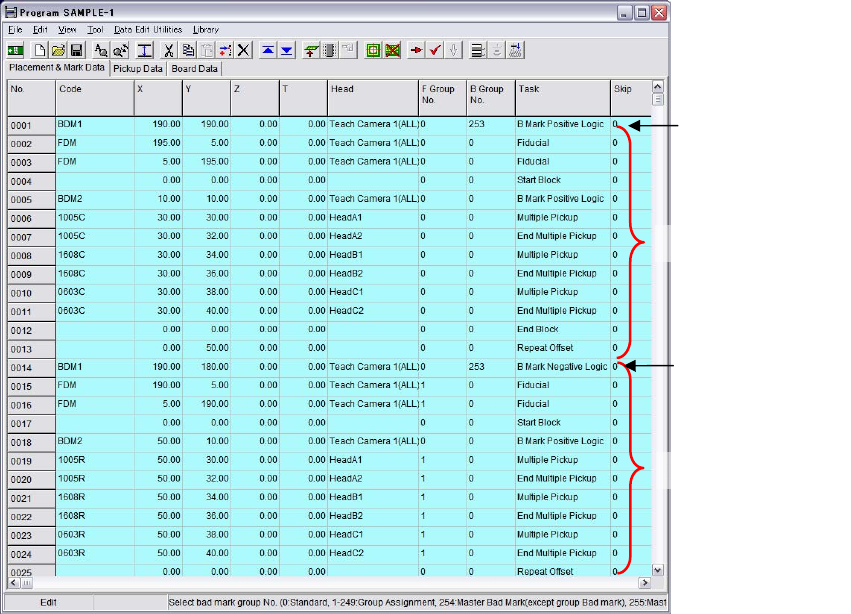
Programming Fiducial Process
For a step to execute fiducial process, enter “Fiducial” to its Task field. Then follow one of the two
programmings stated below:
z Programming 1
For a step to execute global fiducial process, enter “0” (default) to its F Group No. field. For a step
for local fiducial process, enter “1” (fixed). The placement step immediately after a local fiducial
step applies the result in the previous step. Other steps with default “Fiducial=0” apply the result
of the global fiducial process. When there are more than one local fiducial steps with “Fiducial=1”,
each of them represents different local fiducial mark.
z Programming 2
For a step to execute global fiducial process, enter “0” (default) to its F Group No. field. For a step
for local fiducial process, enter “1-249”. The variation “1-249” means that up to 249 fiducial
numbers are available for identifying each local fiducial step. The placement step immediately
after a local fiducial step applies the result in the previous step. Other steps with default “F Group
No.=0” apply the result of the global fiducial process.
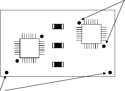
Example5:
Local fiducial
Global fiducial
As shown in the upper figure, suppose to orientate three chips with global fiducial, two ICs with
local fiducial. In this example, for global fiducial, two fiducials are provided, and for local fiducial,
two fiducials for each IC. Programming in use of this example will be as follows:
z Example for Programming 1 (local fiducial number is limited to 0 and 1)
F Group No. Task Description
0 Fiducial Global fiducial process (coordinates assignment)
0 Fiducial Global fiducial process (coordinates assignment)
0 Multiple Pickup Place chip (1) with global fiducial compensation
0 End Multiple Pickup Place chip (2) with global fiducial compensation
1 Fiducial Local fiducial process (coordinates assignment) for IC (1)
1 Fiducial Local fiducial process (coordinates assignment) for IC (1)
1 Single Pickup Place IC (1) with local fiducial compensation
1 Fiducial Local fiducial process (coordinates assignment) for IC (2)
1 Fiducial Local fiducial process (coordinates assignment) for IC (2)
1 Single Pickup Place IC (2) with local fiducial compensation
0 Multiple Pickup Place chip (3) with global fiducial compensation
As shown in the above program, after local fiducial compensation is used for a step, global fiducial
compensation can take effect merely with “Fiducial=0” (default) setting for a later step.
Re-assignment of the global fiducial coordinates is unnecessary.