96722_AX-201 AX-301 AX501 Spec bookl.pdf - 第11页
Each placement robot is fitted with one or more placement heads, which is equipped with Z-height, phi-rotation and real time force control. With every component placement, the placement head measures the impact position …
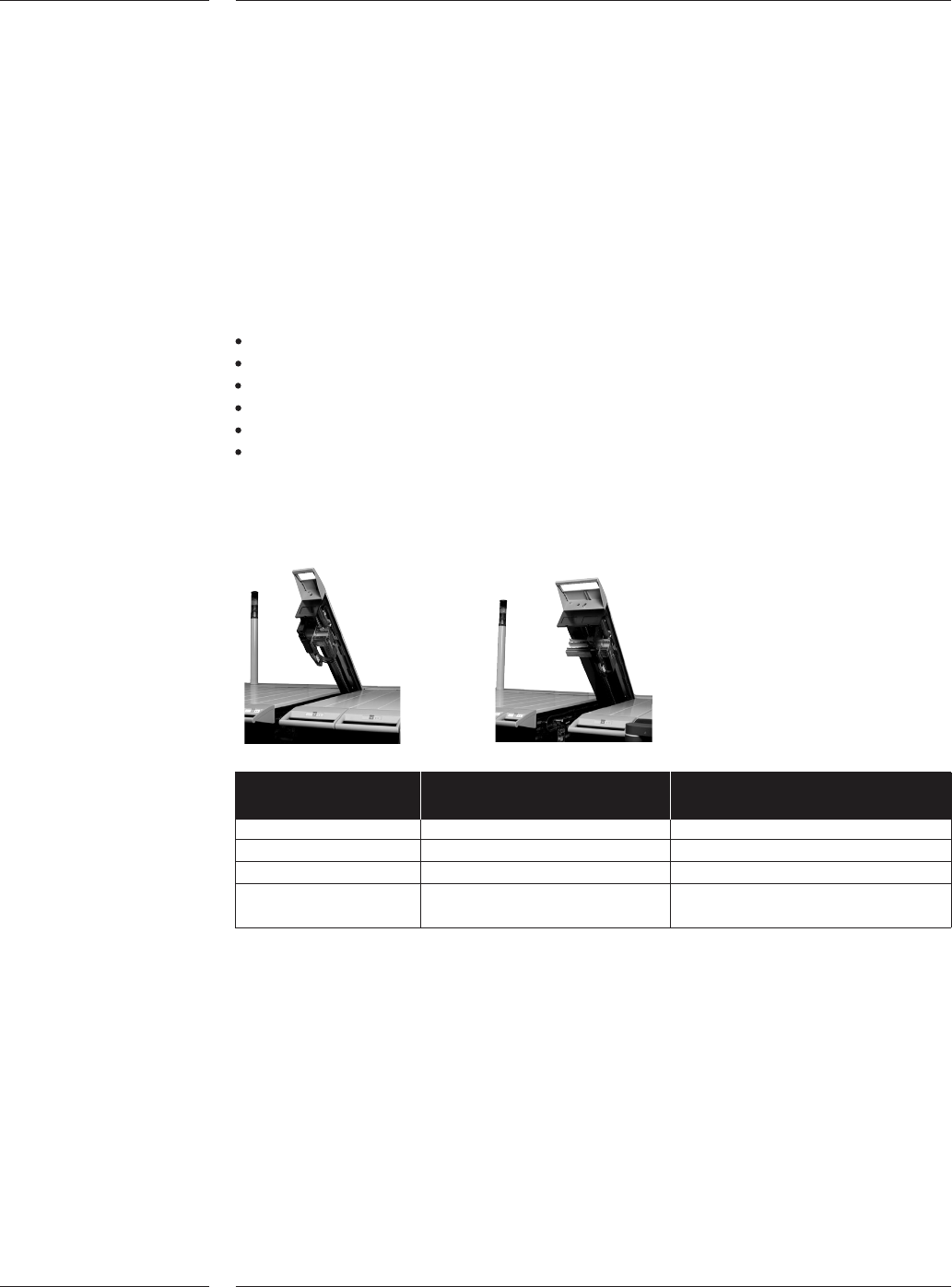
Depending on the base, the machine can be equipped with different types of place-
ment robots; there are three available; the standard placement robot , the compact
placement robot and the X-Y Robot. A compact placement robot is half the width
of a standard placement robot. This allows scaling the machine in output while
maintaining the available feeding positions, and achieving same specifications.
Standard and compact robot specifics:
Direct drive Y spindle using high-resolution rotary encoders
Linear X motor and encoder
Placement head interface
Safety interlocks
Quick exchange connection cables to placement controller
Air controller and local vacuum system (venturi)
The X-Y Robot is an integrated in the machine-base self-calibrating robot with lin-
ear motors and encoders. The H-drive manipulator has two Y-axes and one X-axis.
Please refer to the matrix on page 31 for the base-placement robot relationship.
Standard placement Compact placement
robot robot
Working area 200 x 590mm 80 x 590mm
Weight 52 kg 32 kg
Dimensions (LxWxH) 1625 x 240 x 250mm 1625 x 120 x 250mm
Max. number of
partnumbers 26 11
3.3 Placement
modules
3.3.1.Placement
robot
Figure 2
Features
8 of 34
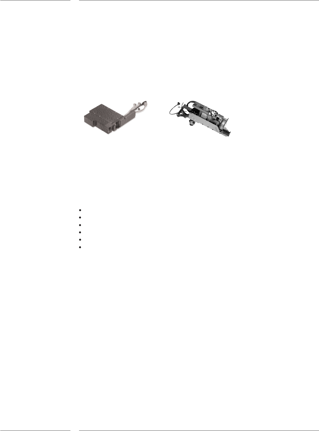
Each placement robot is fitted with one or more placement heads, which is
equipped with Z-height, phi-rotation and real time force control. With every
component placement, the placement head measures the impact position and
calculates the appropriate Z-height to correct for any applicable board warpage.
This adaptive Z-height feature (Board- and component thickness variation
correction) enables that the appropriate placement dwell time and force is well
within the tolerance of process requirements. All placement heads can use vacuum
toolbits for component pick-up, detection and placement.
Placement heads
Four types of placement heads are available:
1. Placement Head Single Vision (PH-SV)
2. Placement Head Laser Vision (PH-LV)
3. Placement Head Dual Vision (PH-DV)
4. Placement Head High Accuracy (PH-HA)
They execute the following tasks:
Align components
Pick and place components
Z-movement
Rz-movement
Force sensing and control
Board- and component thickness variation correction
The Placement Head Single Vision uses a Z-stroke linear motor. This linear motor
controls the pick force, placement Z-speed, dwell time and force. On top of these
control functions, the Placement Head Laser Vision has the capability to perform
component presence check and 'on the fly' laser alignment for components down
to 01005.
The Placement Head Dual Vision (which consists of two placement heads in a single
assembly) is configured in a doubled up configuration, effectively giving four
placement heads. This can pick, rotate and place components with the highest
speed. Component presence as well as the relative position will be checked by the
component vision system.
The Placement Head High Accuracy (configured in a set of two) combines accuracy
with placement forces up to 40N. It also has the capability to detect bent leads of
through-hole components using "variable through hole check". When a lead is bent
the placement head will measure a resistance force when the lead touches the
board. If the force exceeds the programmable limit (between 4 and 14 N) the
component will be rejected. For the most challenging components the PH-HA can
also use mechanical gripper to pick and place components.
3.3.2 Placement
heads
Figure 3
Features
9 of 34
Placement Head Placement Head Placement Head Placement Head
Single Vision Laser Vision Dual Vision High Accuracy
Maximum stroke 27mm 27mm 40mm 77mm
Placement force Programmable Programmable Programmable Programmable
between 1.5 - 8N between 1.5 - 8N between 2 - 8N between 0.9- 40N
in 0.1N steps
*1
in 0.1N steps
*1
in 0.1N steps in 0.1N steps
*1
Lower forces down
to 0.06N with
restrictions
Variable through Not applicable Not applicable Not applicable Programmable
hole check between 4 and
14 N
Configured in One One Two (four heads Two heads
set of: in total) in total
Toolbits Nozzles Nozzles Nozzles Nozzles and
grippers
*1 Depending on nozzle type
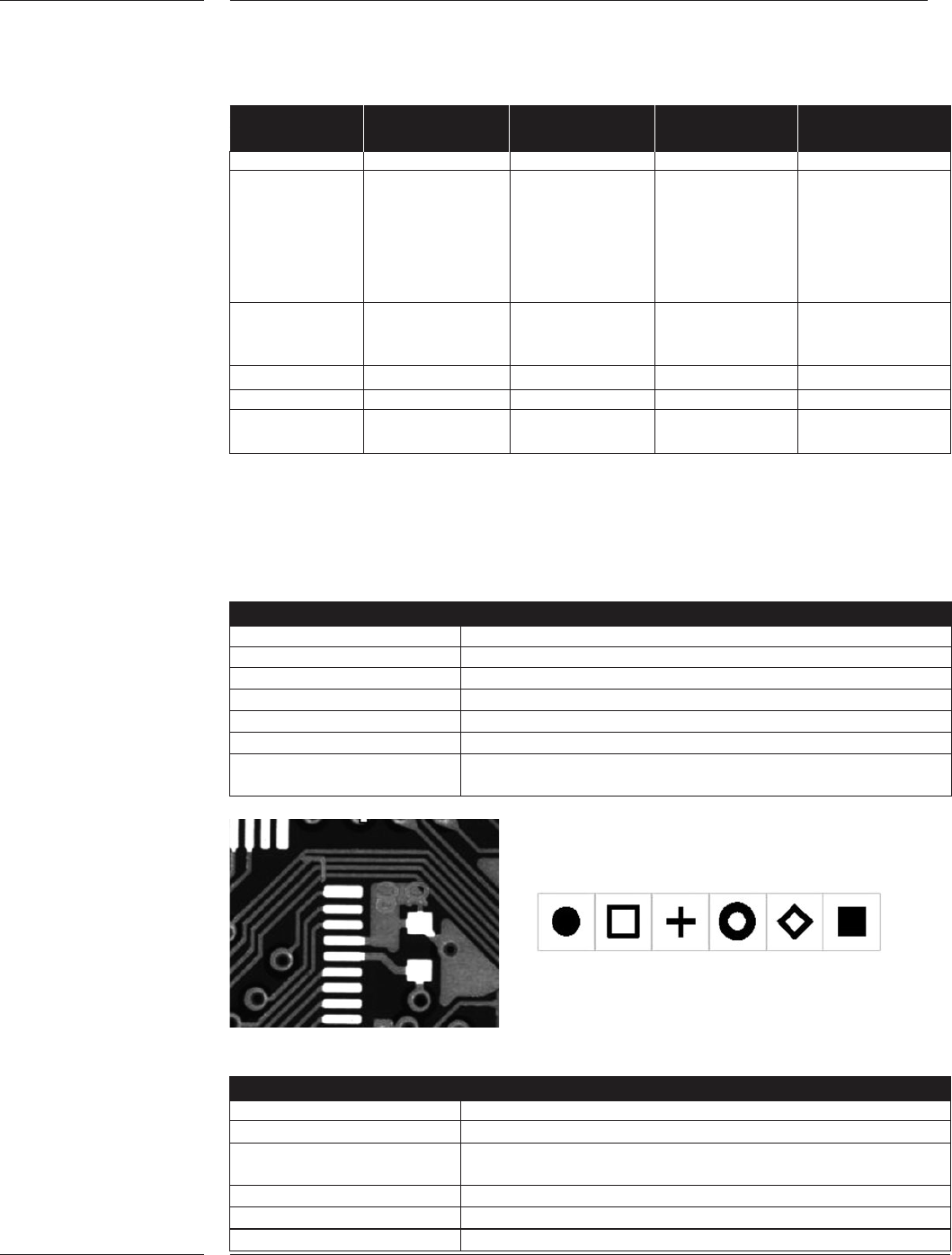
The board alignment camera is used for fiducial and artwork alignment, and is also
used for badmark sensing, position detection of feeder trolleys, toolbit exchange unit,
dump bin and the component vision camera.
Board alignment camera
Camera Field of View 8.6 x 6.8mm
Camera pixels 1024 x 768
Camera pixel resolution 8.4 µm
Illumination Bright field & dark field
Fiducial types All regular types with a contrast level of >30%
Fiducial shape size Fiducial shape size >0.3mm, <3.0 mm
Free zone around fiducial No features allowed within 0.1mm, no look-a-likes
within 2.6mm from fiducial
Examples of artwork and typical fiducials
Badmark sensing
Bad mark type Black or white dot, or fiducial shape
Size >φ 1mm
Color Bad marks can be dark in a light background or light in
a dark background
Contrast At least 30 %
Badmark levels 3
Number of bad marks <2048
per board
3.4 Board
alignment
Figure 4
Features
10 of 34