96722_AX-201 AX-301 AX501 Spec bookl.pdf - 第15页
Each placement robot requires a toolbit exchange unit to exchange toolbits automatically. In less than one second a toolbit is exchanged, while production continues. Holding multiple positions a maximum flexibility for c…
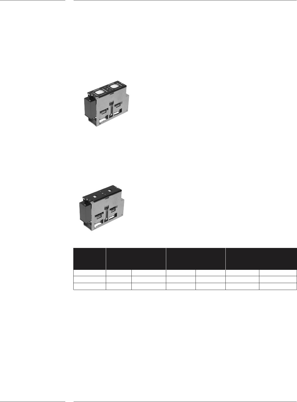
LFOV is holding two upward looking cameras. It is used to align and inspect a wide
range of components up to 45 x 45 mm or 66 x 23 mm with bump or lead width
down to 150 micron. The maximum component size for components picked with
the Placement Head Dual Vision is 21 x 21 mm as four components can be
inspected at the same time. Components up to 165 x 45mm can be measured with
restrictions.
LFOV
SFOV is also holding two upward looking cameras and is used for ultra fine pitch
components like CSPs and flip chips. By use of a smaller field of view (22x22mm)
a higher accuracy can be achieved. The SFOV can be used with the Placement
Head High Accuracy and can align two components at the same time.
SFOV
Camera Maximum Lead Bump
component size
*1
X-axis Y-axis Width Pitch Size Pitch
CV CAMERA 45 45 0.200 0.400 0.300
*2
0.500
*2
LFOV 45 45 0.150 0.300 0.150 0.300
SFOV 22 22 0.080 0.160 0.080 0.160
Note: Component and lead dimensions above or below the noted specification require
an application review.
*1
: Components larger than the noted size can be processed. The CV LFOV can measure
a 165mm long connector, however some restrictions may apply. Also components of
66x23mm (or 23x66mm) can be measured in one view using the Placement Head
High Accuracy.
*2
: For components < 12x12mm, minimum bump size can be 0.150, the minimum pitch
can be 0.300
3.5.2.2 Component
vision Large
Field of View
camera
Figure 6
3.5.2.3 Component
vision Small
Field of View
camera
Figure 7
Features
12 of 34
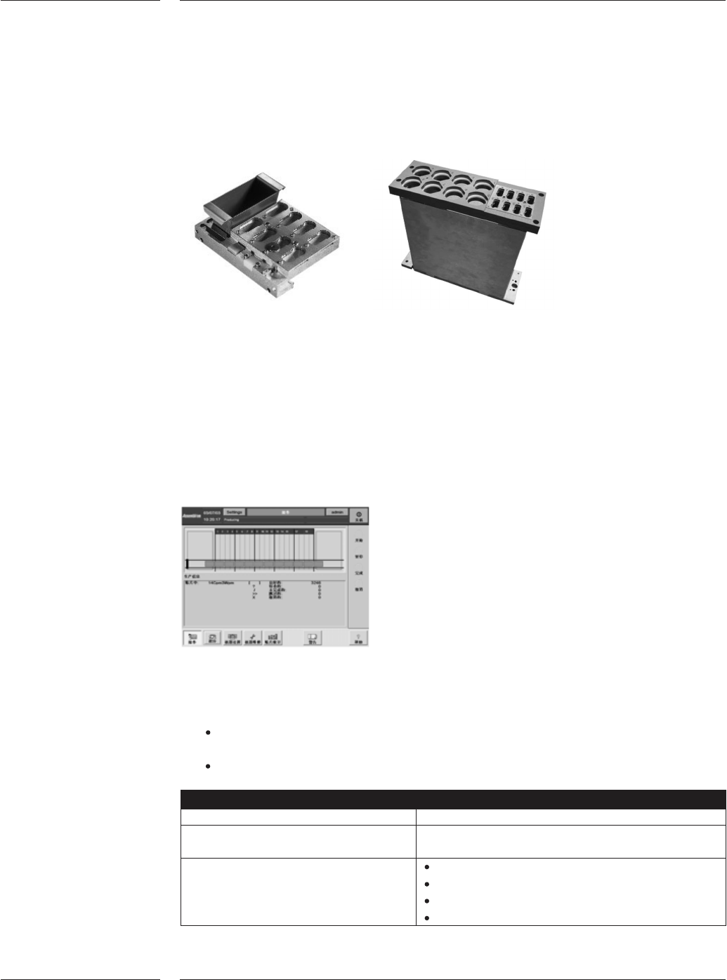
Each placement robot requires a toolbit exchange unit to exchange toolbits
automatically. In less than one second a toolbit is exchanged, while production
continues. Holding multiple positions a maximum flexibility for component range
and family setup is ensured
AX Toolbit exchange unit and dump bin
The A-Series is operated via a touch screen and a full graphical user interface. The
user interface complies to SEMI E95 to maximize ergonomics, ease of use and
minimize learning time. The interface can be set to different language modes. This
can be done while the production is running and is therefore, suited to multi-lingual
environments.
A wide range of languages is standard available, please check with the local
Assembléon representative for more details. All other languages can be made
available upon request.
Chinese Graphical User Interface
Board Identification (BI) can be used to provide barcode -ID and traceability
information. It features:
A check of the board ID versus the running placement program. On error the
system will block the board from entering the machine.
Board identification for traceability (see paragraph on traceability).
Barcode specifications
Types 1D and 2D
Length 1D: max. 1024
2D: to ISO/IEC 16022
Codes CODE39
2/5 Interleaved
CODE128
Data matrix ECC200
3.6 Toolbit
exchange
unit
Figure 8
3.7 User
interface
Figure 9
3.8 Board
Identification
Features
13 of 34
Scanner specifications
Connection RS-232
Baudrate 9600 kb/s
Number of bits 7
Stopbit 1
Parity bit none
X-on/X-off off
Note: There are no scanners provided with the system.
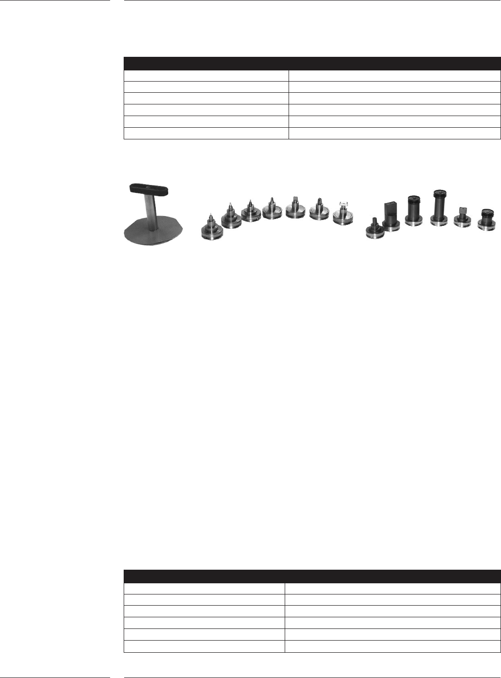
The A-Series uses a variety of toolbits to handle the wide range of components from
0.4 x 0.2mm (01005) up to 165mm long connectors. Each toolbit is designed to
ensure durability, minimal wear, whilst providing robust and delicate component
handling. The toolbits are connected to the placement head by a magnetic
connection or mechanical clamping.
Please refer to the Compatibility matrix on page 32 for an overview of the toolbit
and placement head relationship as well as the toolbit and component relationship.
Toolbits for the PH-SV, PH-LV and PH-DV
The magnetic connection between toolbit and placement head allows fast and
automatic exchange of the toolbit while ensuring a firm connection.
Toolbits for the PH-HA
The standard toolbits for the PH-HA incorporate two toolbits in one. This is referred
to as “dual telescoping toolbits”. There are 5 different outer toolbits, each of
different diameters. Located inside the outer toolbit, a choice of up to 5 inner
toolbits can be used thereby allowing a wide range of components to be placed
using the same placement head.
Mechanical grippers are available to pick and place components which cannot be
picked using vacuum toolbits. The standard gripper set contains a basic gripper with
3 jaw sets that can be adapted by the user to comply with the specific shape of the
component being placed.
Gripper
Max. component size 165 x 45mm
Max. component height 40mm (with restrictions)
Max. weight 50 gram
Clamp force 6.5 ± 0.5N
Placement force 4 - 40N
Variable through hole check 4 - 14N
4.0 Options
4.1 Toolbits
Figure 10
Options
14 of 34