WaferTransportSolutionManual.pdf - 第100页
INSTALLATION EQUIPMENT INSTALLATION 3.24 Wafer Transport Solutio n Chapter Issue 1 Aug 11 NOTE All setting bars are marked with unique readings expressing the bar ’s flatness. The centre reading is always zero, the other…
INSTALLATION
EQUIPMENT INSTALLATION
Chapter Issue 1 Aug 11 Wafer Transport Solution 3.23
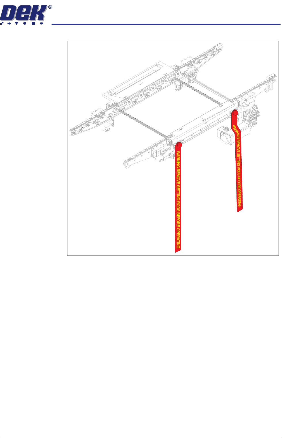
Figure 3-9 Setting Rods Fitted Through Both Rails
12. Activate the E Stop.
13. Remove the Pallet and Shim.
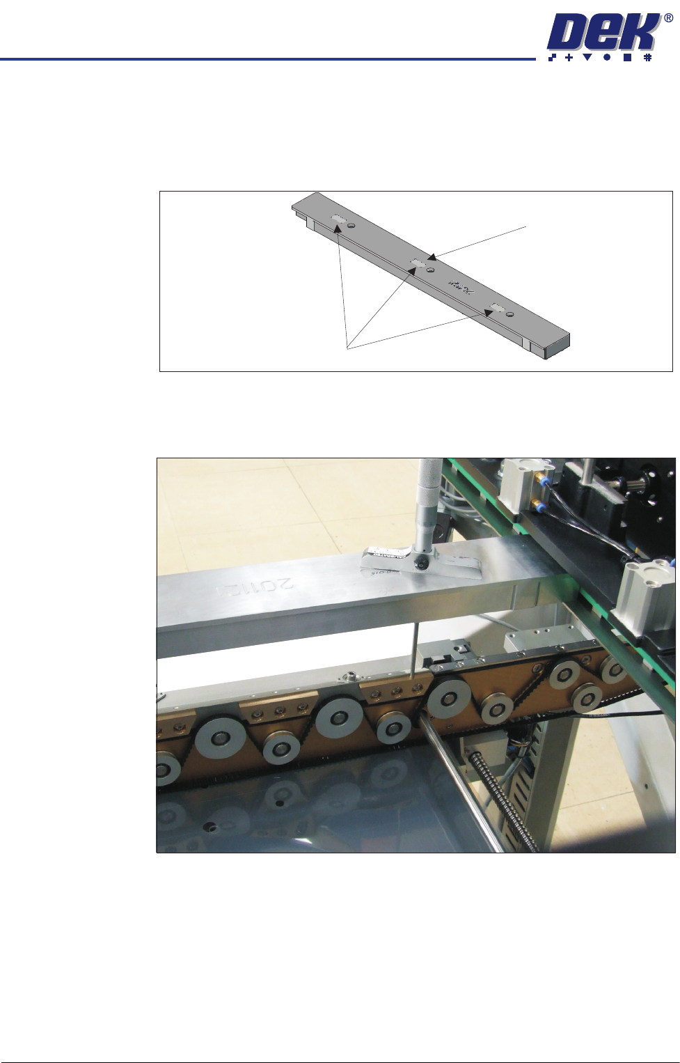
14. Align setting bar (201121) in the chase, with the holes over the front rail.
15. Insert the depth micrometer into the left/right holes of the setting bar;
touching the support blocks.
16. Note the reading of the depth micrometer to the support blocks.
INSTALLATION
EQUIPMENT INSTALLATION
3.24 Wafer Transport Solution Chapter Issue 1 Aug 11
NOTE
All setting bars are marked with unique readings expressing the bar’s
flatness. The centre reading is always zero, the other readings are relative
to the centre. These markings are known as the setting bar flatness
calibration figures.
17. Remove the depth micrometer.
18. Insert the depth micrometer into the left hole of the setting bar. The depth
micrometer tip contacts the left hand pallet support block.
Setting Bar Flatness Calibration Figures
Centre is Zero (0.00)
INSTALLATION
EQUIPMENT INSTALLATION
Chapter Issue 1 Aug 11 Wafer Transport Solution 3.25
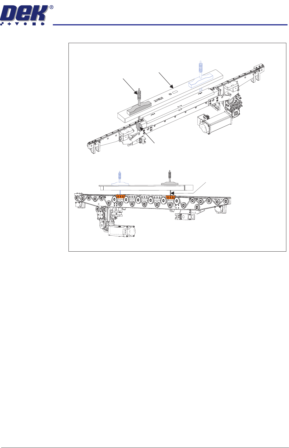
19. Test at the lowest point (described by the pallet rock).
At points found to be low, which could affect pallet rock; make adjustments
to the rail height adjusters.
View on Front Left Quarter of the Front Rail
View on the Rear of the Front Rail
Depth Micrometer
Depth Micrometer
(Location 2)
Rail Height Adjuster
Setting Bar
Micrometer readings taken
from the top surface of the
pallet support blocks as shown