WaferTransportSolutionManual.pdf - 第29页
HEAVY PALLET RAILS ADJUST MENTS & SE TTINGS Chapter Issue 1 August 11 Wafer Transport Solutio n 1.21 8. Place two tooling pins behind the front rail as shown below . 9. Ensure that the camera is parked at the far lef…
HEAVY PALLET RAILS
ADJUSTMENTS & SETTINGS
1.20 Wafer Transport Solution Chapter Issue 1 August 11
Rail Parallelism
Front Rail Alignment Open the front printhead cover and check that the tooling table is completely
clear before starting this procedure.
1. On the user interface navigate to the Diagnostics page.
2. Select Rail System.
3. Select Toggle Heavy Rail Drop; ensure the rail lowers when ON and lifts
when OFF.
4. Select Toggle Board Clamp; ensure the rail moves inwards and lowers.
5. Select Drive Camera to Heavy Rail Alignment. Run the diagnostic.
6. Select Continue.
The following actions occur:
• The rear rail drives to the home position
• The camera moves to a central location
• The table rises
• The NextMove controller instigates a soft E-Stop allowing the camera to
be manually moved
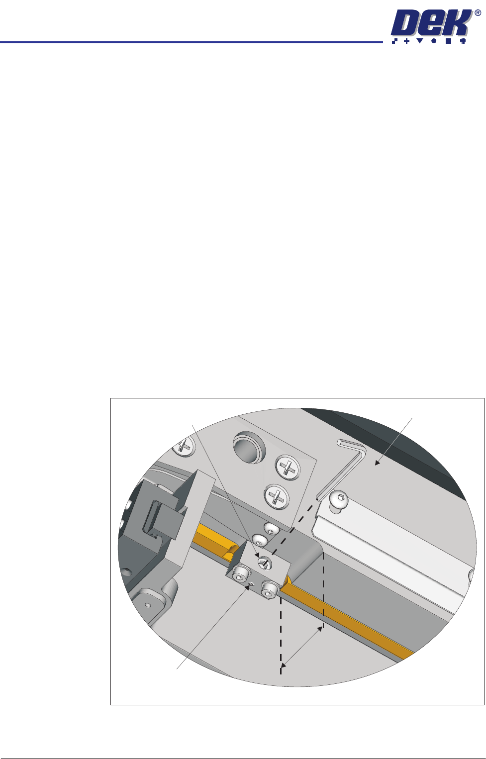
7. Check that the two adjuster blocks, under the rail, abut the rising table front
face but do not foul it. There should be 44mm from the front face of the table
tooling plate to the front face of the rail.
44mm
View on Underside of Front Rail, Left Hand Side
Rail Front Face
Locking Grubscrew
Adjustment Set Screw
HEAVY PALLET RAILS
ADJUSTMENTS & SETTINGS
Chapter Issue 1 August 11 Wafer Transport Solution 1.21
8. Place two tooling pins behind the front rail as shown below.
9. Ensure that the camera is parked at the far left location of the camera beam.
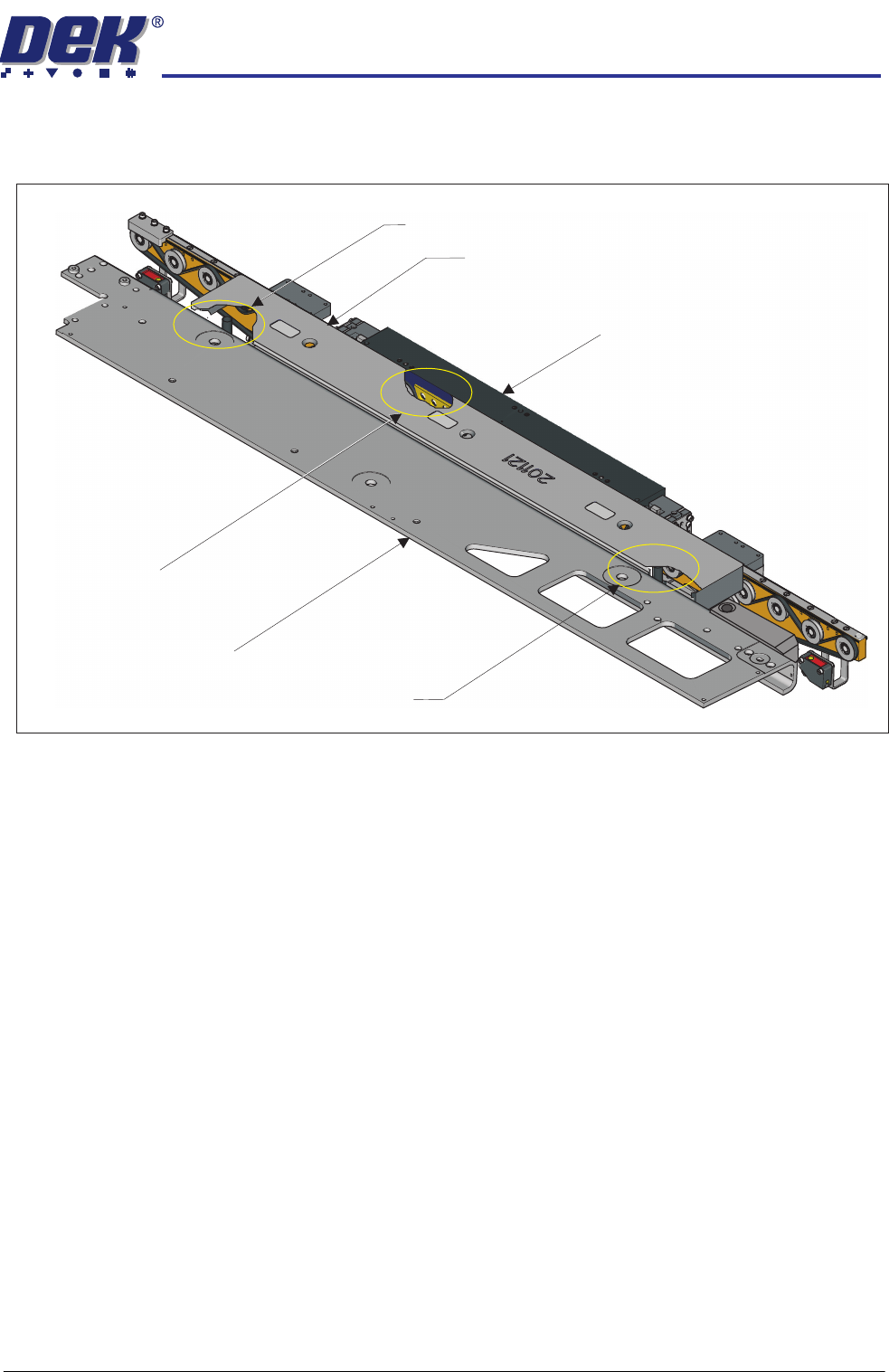
10. Sit the setting bar (201121) on the tooling pins and the rail support blocks.
11. Pull the camera beam toward the setting bar until it just touches the bar.
12. Press the System button.
13. Select Toggle Heavy Rail Drop. This action lowers the setting bar onto
the front rail support blocks; the belts are lowered out of the way.
Cut-away showing a tooling pin
used to support the setting bar
Cut-away showing a rail support block
used to support the setting bar
Cut-away showing a tooling pin
used to support the setting bar
Front Rail
Setting Bar
Camera Beam
HEAVY PALLET RAILS
ADJUSTMENTS & SETTINGS
1.22 Wafer Transport Solution Chapter Issue 1 August 11
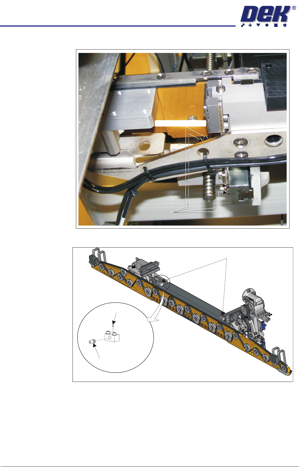
14. Release the four left hand bearing mount grubscrews.
15. Loosen the right-hand adjuster block locking grubscrew.
Grubscrews
Grubscrews (at rear)
View on Underside of the Front Rail
Adjuster Blocks
Locking
Grubscrew
Adjustment
Screw