WaferTransportSolutionManual.pdf - 第43页
HEAVY PALLET RAILS ADJUST MENTS & SE TTINGS Chapter Issue 1 August 11 Wafer Transport Solutio n 1.35 10. Select Diagnostics . 1 1. Select Rail System . 12. Select Select Module . 13. Select T oggle Heavy Rail Drop . …
HEAVY PALLET RAILS
ADJUSTMENTS & SETTINGS
1.34 Wafer Transport Solution Chapter Issue 1 August 11
1. Ensure that the screen has been removed from the printer.
2. Ensure that the pallet and shim have been removed from the printer.
3. Select Setup Product.
4. Select Board Length Board Width.
5. Select Board Width. Set the board width to match the pallet.
6. Select Board Length. Set the board length to match the pallet.
7. Select Accept.
8. Select Back.
9. Select Maintenance.
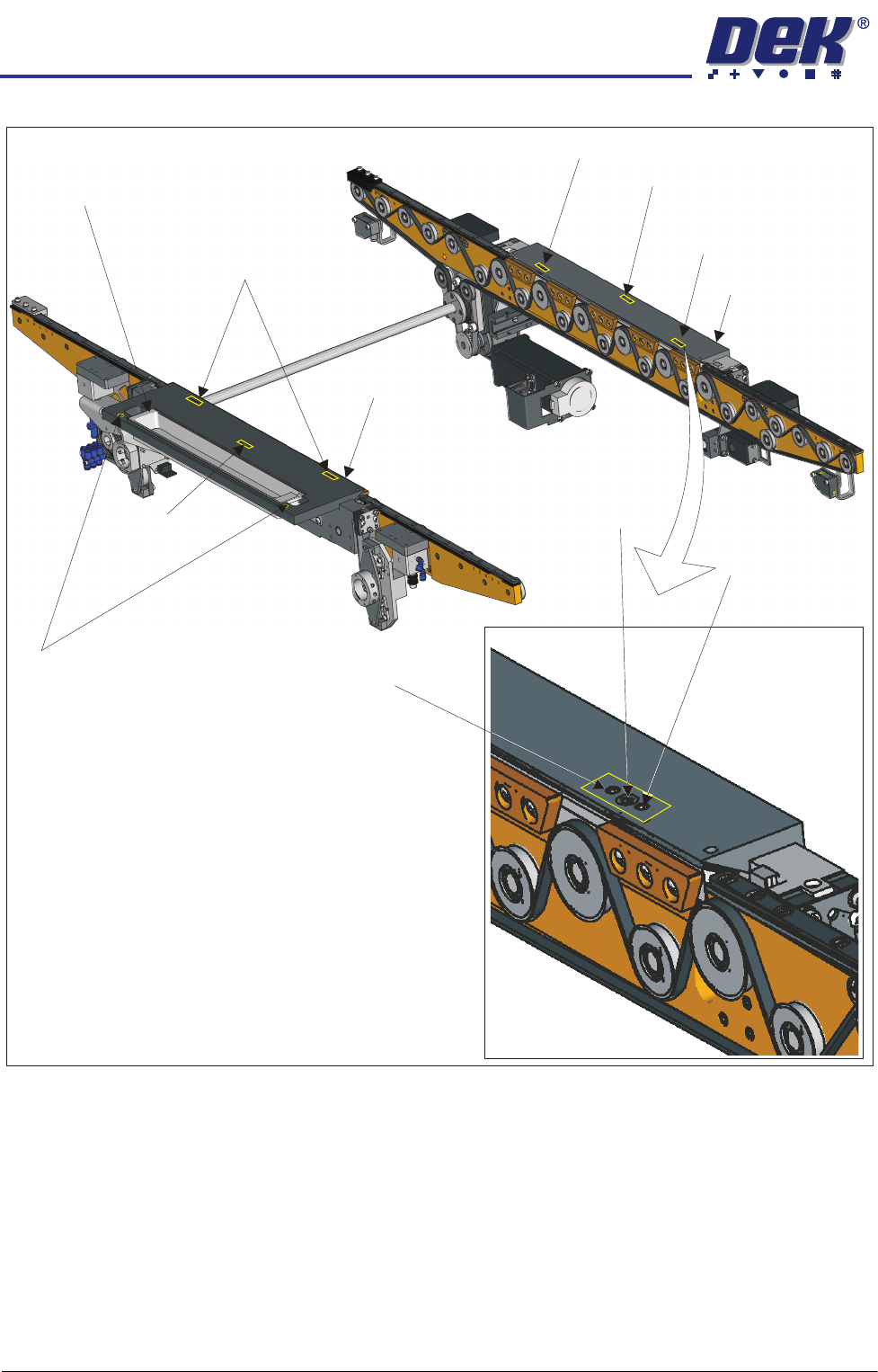
Adjustment (1) Screws (2)and Locking
Sphere Dump Tray
Rear Top Plate
Front Top Plate
Locking Screw
Locking Screw
Adjustment (1) and Locking Screws (2)
Adjustment (1) Screw
Adjustment (1) Screw
Safety Screws (2)
Adjustment (1)
Locking
and
Screws (2)
Adjustment Screw

HEAVY PALLET RAILS
ADJUSTMENTS & SETTINGS
Chapter Issue 1 August 11 Wafer Transport Solution 1.35
10. Select Diagnostics.
11. Select Rail System.
12. Select Select Module.
13. Select Toggle Heavy Rail Drop.
14. Select Run Diagnost..
15. Open the printhead front cover. The software pauses and displays the
System Error - System Suspended While Covers Open Warning.
16. Move the print carriage to the rear of the printer.
17. Load the pallet and shim into the print area.
18. Carefully run a finger along the length of the top plates (front and rear) and
check for any areas where adjustment is needed.
19. Loosen the six locking screws (on each rail) and adjust the three adjustment
screws on the top plates so that the top plate matches the pallet height.
20. Tighten the locking screws.
HEAVY PALLET RAILS
ADJUSTMENTS & SETTINGS
1.36 Wafer Transport Solution Chapter Issue 1 August 11
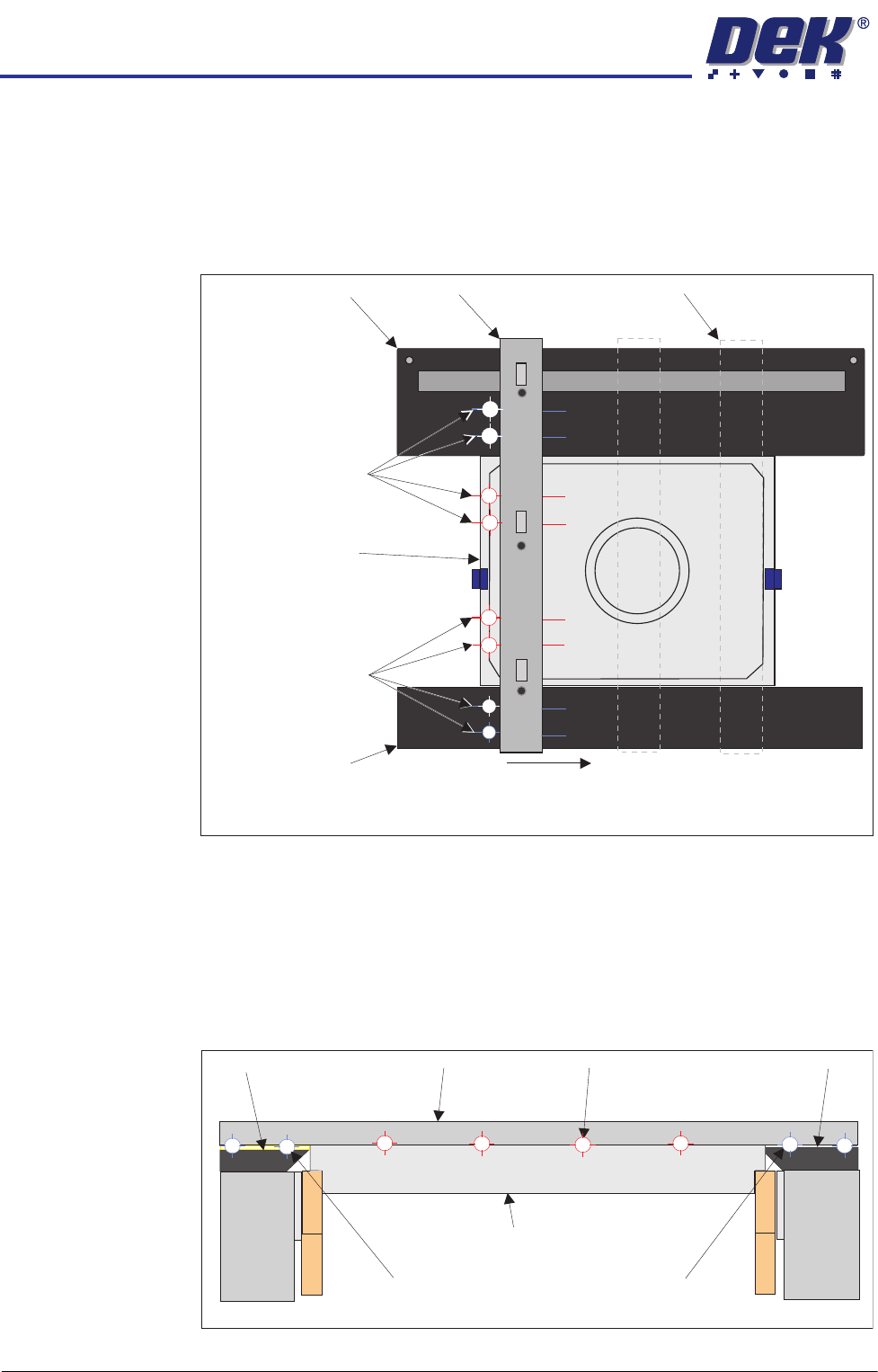
21. Carefully place the setting bar across both rails covering the pallet and shim
at three points:
• Left hand edge
• Centre
• Right hand edge
22. A 0.05mm feeler gauge is used to check that any gap, between the top
plates and the setting bar, is not greater than 0.05mm. Measurements
should be made at similar locations to those shown in the graphic above.
For each location, slide a feeler gauge between the setting bar and: the top
plates, the pallet and the shim. On the top plates, the gap should be as
detailed below (outer target areas [1,2,7&8]). For the areas between the
setting bar and the pallet/shim (inner target areas [3,4,5&6]) it should not be
possible to insert the feeler gauge.
23. Make fine adjustment to the rail height adjustment set screws to give a flat
Pallet Shimand
Carefully position the setting bar at the left, centre and
right positions to make the measurements.
Front Transport Rail
Rear Transport Rail
Setting Bar
Measurement
Locations
(both sides of the bar)
Measurement
Locations
(both sides of the bar)
Setting Bar (at end location)
1
2
3
4
5
6
7
8
View on Right Hand Side of Rails
Customer Pallet and Shim
Setting Bar
Top Plate Top Plate
Gap = 0.05mm
Gap < 0.05mm
Gap = 0.05mm
Front Rail
Rear Rail
1
2
3
4
5
6
7
8