WaferTransportSolutionManual.pdf - 第36页
HEAVY PALLET RAILS ADJUSTMENTS & SETTINGS 1.28 Wafer Transport Solutio n Chapter Issue 1 August 11 8. Using Decr . or Incr . navigate to Raise T able to Vision Height 9. Select Run Diagnost. . 10. Open the printhead …
HEAVY PALLET RAILS
ADJUSTMENTS & SETTINGS
Chapter Issue 1 August 11 Wafer Transport Solution 1.27
Pallet to Rail Alignment
WARNING
HEAVY OBJECT. EXTREME CAUTION SHOULD BE EXERCISED WHEN
MANUALLY HANDLING HEAVY ITEMS INTO OR OUT OF THE MACHINE.
Reference Check NOTE
The precision pallet, shim, rail top plates and setting bar are all manufactured
to a high degree of flatness and are susceptible to surface flaws that can
degrade their function. In the following procedure hard tooling is used in contact
with these surfaces which may cause markings or more significant damage, if
not handled carefully. Tooling used must be clean and blemish free. All effort
must be made to avoid dragging, dropping or knocking tools on the exposed
surfaces.
For many instances, this check gives the level of accuracy required to produce
good quality prints; for the highest accuracy, carry out this check and the
accuracy check, refer to the section - Accuracy Check for details.
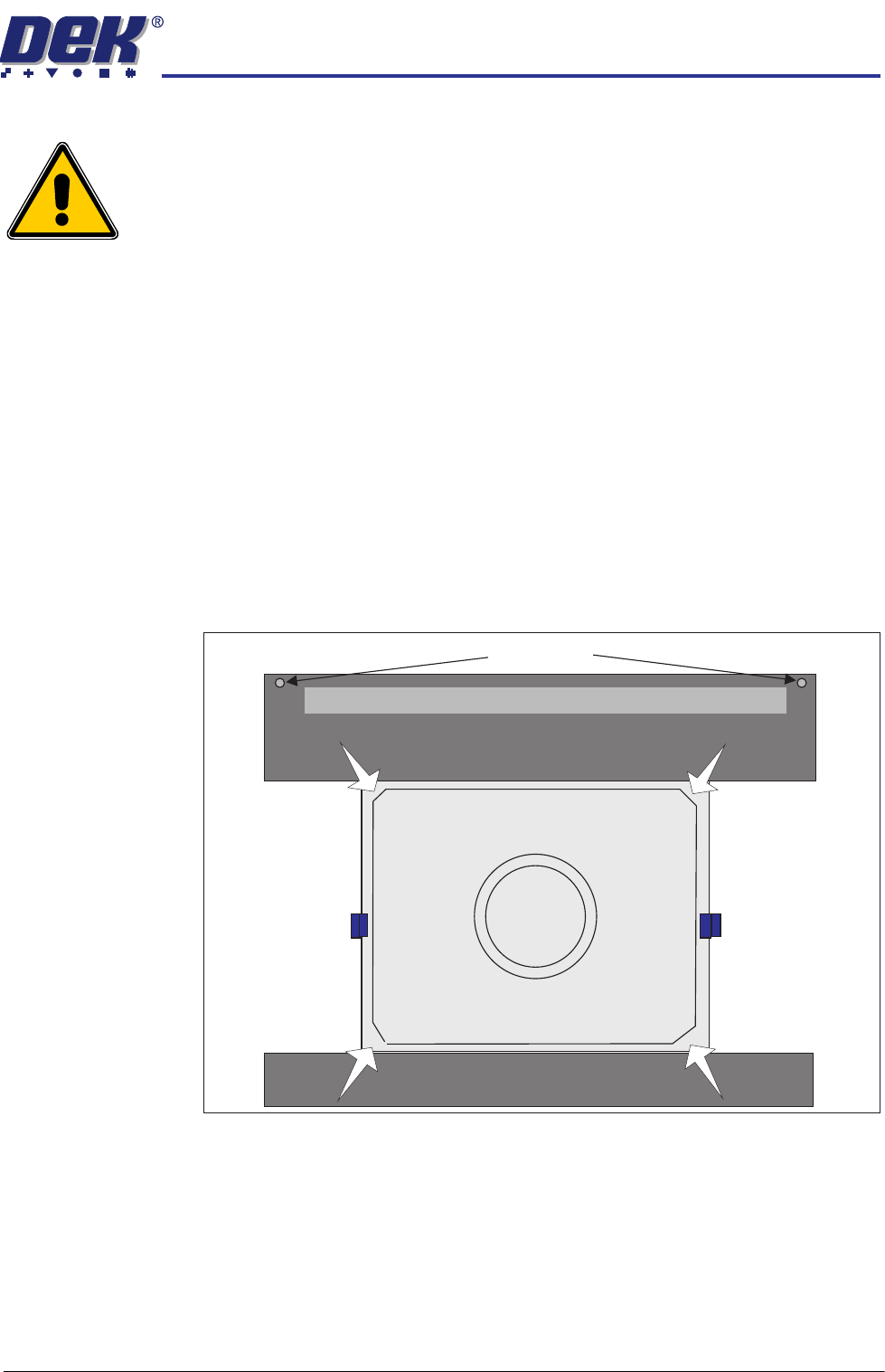
1. Press the pallet down in each of the four corners and check for any rocking
movement; if rocking is noted, complete the following steps; for no rocking,
continue with the accuracy check.
2. Close the front printhead cover.
3. Remove the sphere dump tray from the rear transport rail; retain for later
refit.
4. Press the System button.
5. Select Exit.
6. Using Decr. or Incr. navigate to Rising Table.
7. Select Select Module.
Pallet Shimand
Front Transport Rail
Rear Transport Rail
Safety Screws
Sphere Dump Tray Removed
HEAVY PALLET RAILS
ADJUSTMENTS & SETTINGS
1.28 Wafer Transport Solution Chapter Issue 1 August 11
8. Using Decr. or Incr. navigate to Raise Table to Vision Height
9. Select Run Diagnost..
10. Open the printhead front cover. The software pauses and displays the
System Error - System Suspended While Covers Open warning.
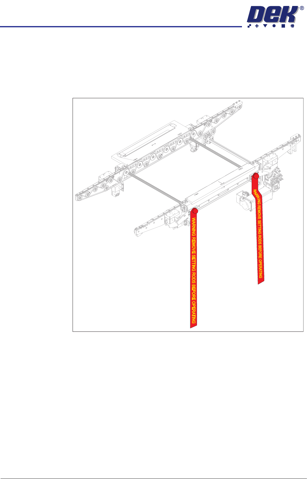
11. Fit the two setting rods.
Figure 1-6 Setting Rods Fitted Through Both Rails
12. Activate the E Stop.
13. Remove the Pallet and Shim.
14. Slacken the three clamp locking screws on both sides of the front and rear
rails, sufficient enough to allow adjustment. Maintain enough preload to
HEAVY PALLET RAILS
ADJUSTMENTS & SETTINGS
Chapter Issue 1 August 11 Wafer Transport Solution 1.29
keep the clamp fixings in contact with the beam ends.
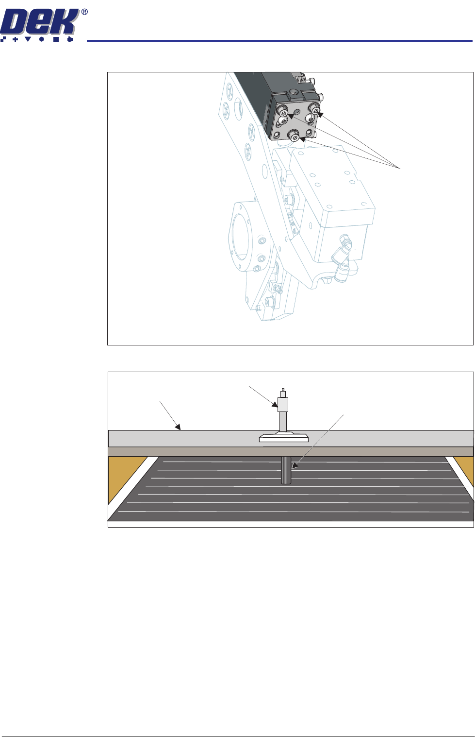
15. Place a tooling pin in the centre of the tooling table.
16. Align setting bar (201121) in the chase, with its centre hole over the tooling
pin.
17. Insert the depth micrometer into the centre hole of the setting bar touching
the tooling pin top.
18. Note the reading of the depth micrometer to the tooling pin.
Locking Screws
View on Left Hand End of the Rear Rail
Setting Bar
Depth Micrometer
Tooling Pin