WaferTransportSolutionManual.pdf - 第79页
INSTALLATION OVERVIEW Chapter Issue 1 Aug 11 Wafer Transport Solutio n 3.3 Figure 3-3 A T ypical CHAD Production Layout CHAD W aferMate with DEK Printers and Oven Line CHAD W aferMate Oven FOUP (W afer Stack)
INSTALLATION
OVERVIEW
3.2 Wafer Transport Solution Chapter Issue 1 Aug 11
NOTE
1. DEK Printer installation instructions are detailed in the printer’s specific
Installation manual. Follow the procedures laid out in the installation manual
in conjunction with these application specific instructions.
2. The DEK Printer can interface with an upline pallet transfer station; currently
DEK recommend the use of equipment from either: CHAD Industries, a fully
automatic system, or NUTEK a semi-automatic system.
3. The heavy pallet transport rails are fixed directly to the printer’s rising table;
transport height is not determined by the position of the clatter bars, as
described for standard DEK printing machines.
4. A complete system may consist of:
a. A DEK printer used for printing flux
b. A pallet transfer station or a manual load area
c. A DEK printer used for depositing spheres
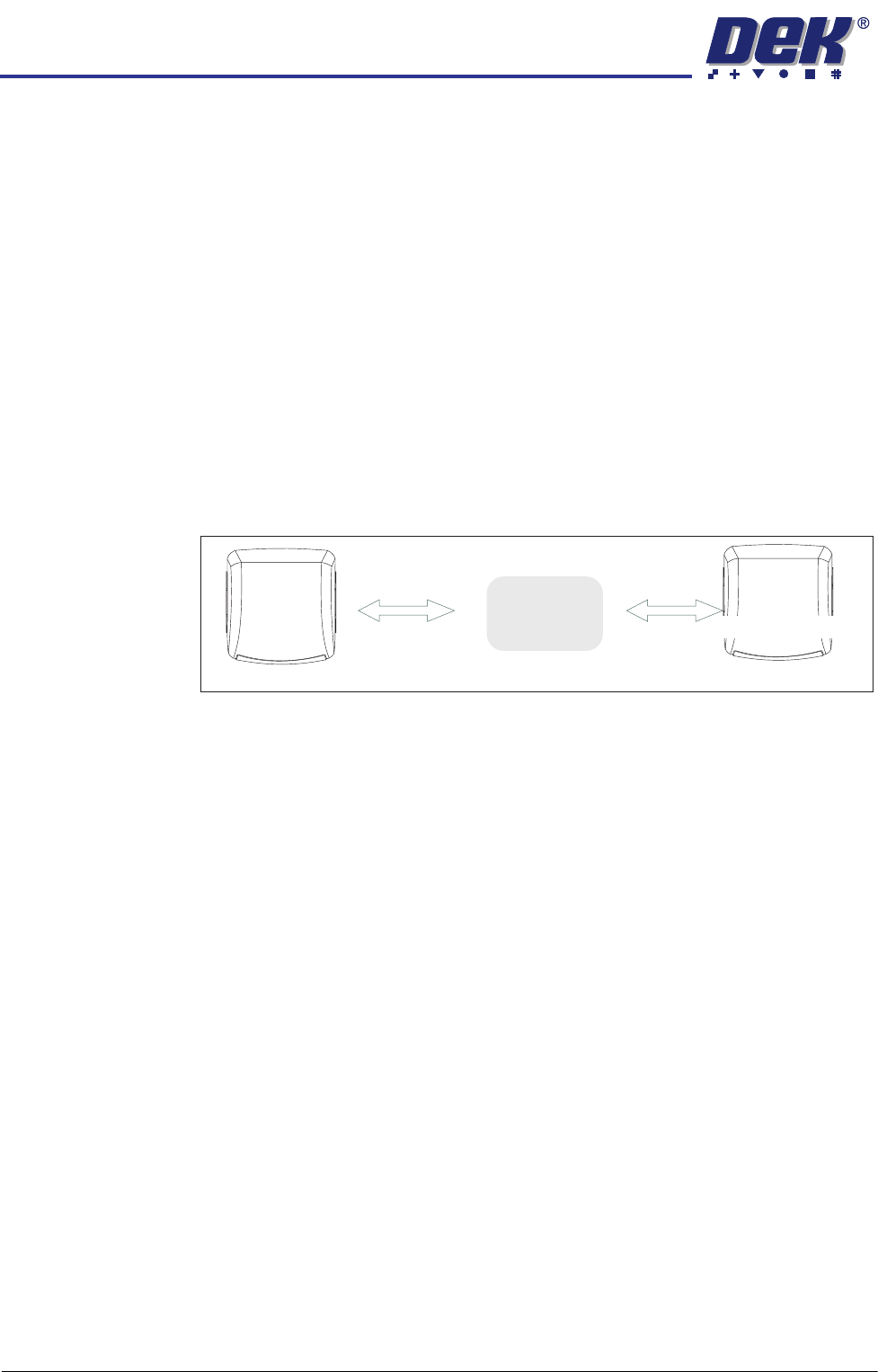
Figure 3-2 A Typical NUTEK Production Layout
Downline Upline
DEK
Machine
(Flux Print)
DEK
Machine
(Sphere Attach)
Upline
Transfer
Station
INSTALLATION
OVERVIEW
Chapter Issue 1 Aug 11 Wafer Transport Solution 3.3
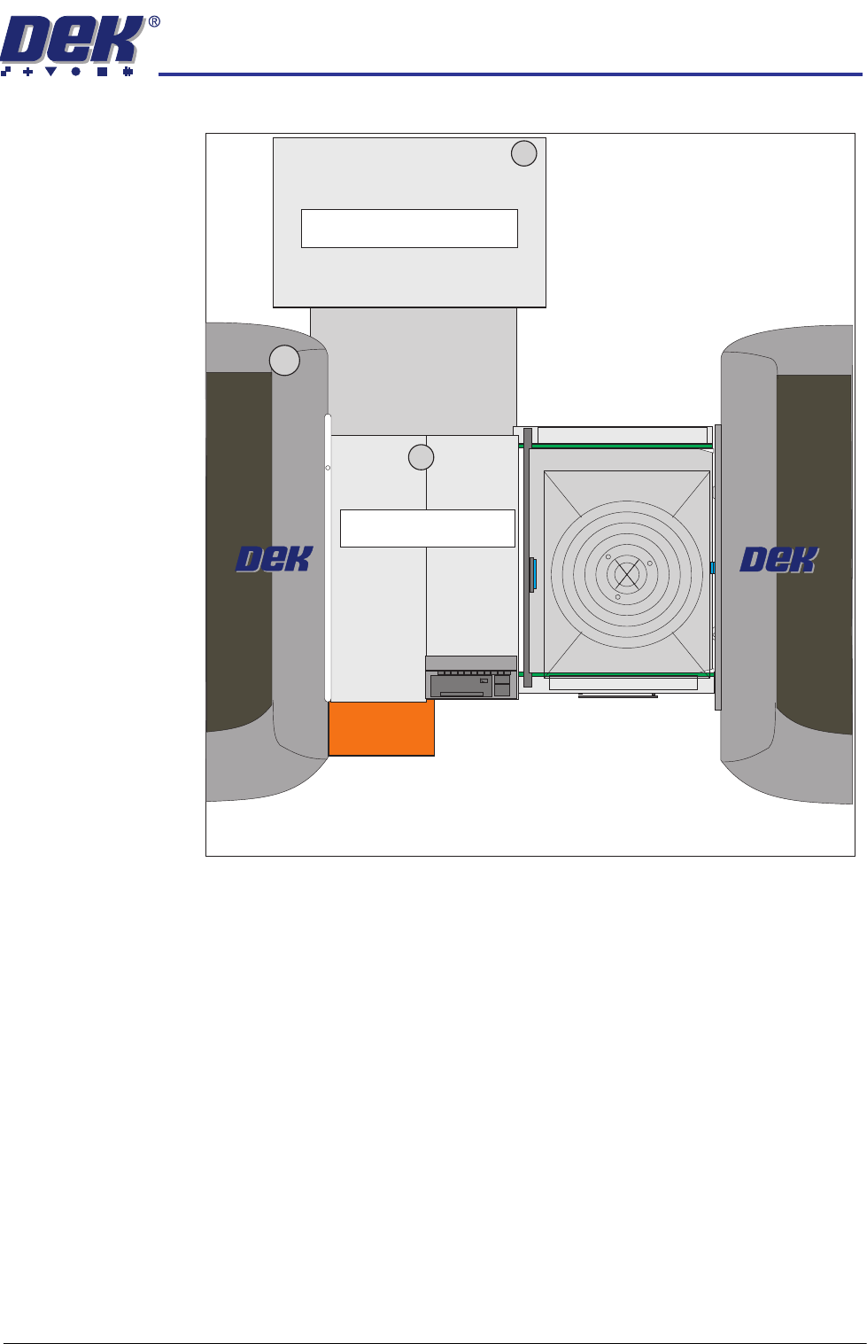
Figure 3-3 A Typical CHAD Production Layout
CHAD WaferMate with DEK Printers and Oven Line
CHAD WaferMate
Oven
FOUP
(Wafer Stack)
INSTALLATION
OVERVIEW
3.4 Wafer Transport Solution Chapter Issue 1 Aug 11
Safety Users must comply with machine safety warnings and notices as listed in the
various equipment manuals. The following safety instructions give additional
notices relevant to this application.
Pallets loaded into the printer and transfer stations can be up to 15Kg in
weight. Operators and maintainers should take care to use the correct lifting
practices when lifting pallets into and out of the printer, and/or the downline
pallet transfer station, or other equipment in the line.
Equipment Safety
Covers
The printer is designed with safety covers fitted to the printer’s side covers. In
normal operation, the covers prevent users from accessing areas where they
can be exposed to hazards. The printer can be operated in the following input/
output modes:
• Left to Right
• Right to Left
• Left to Left
• Right to Right
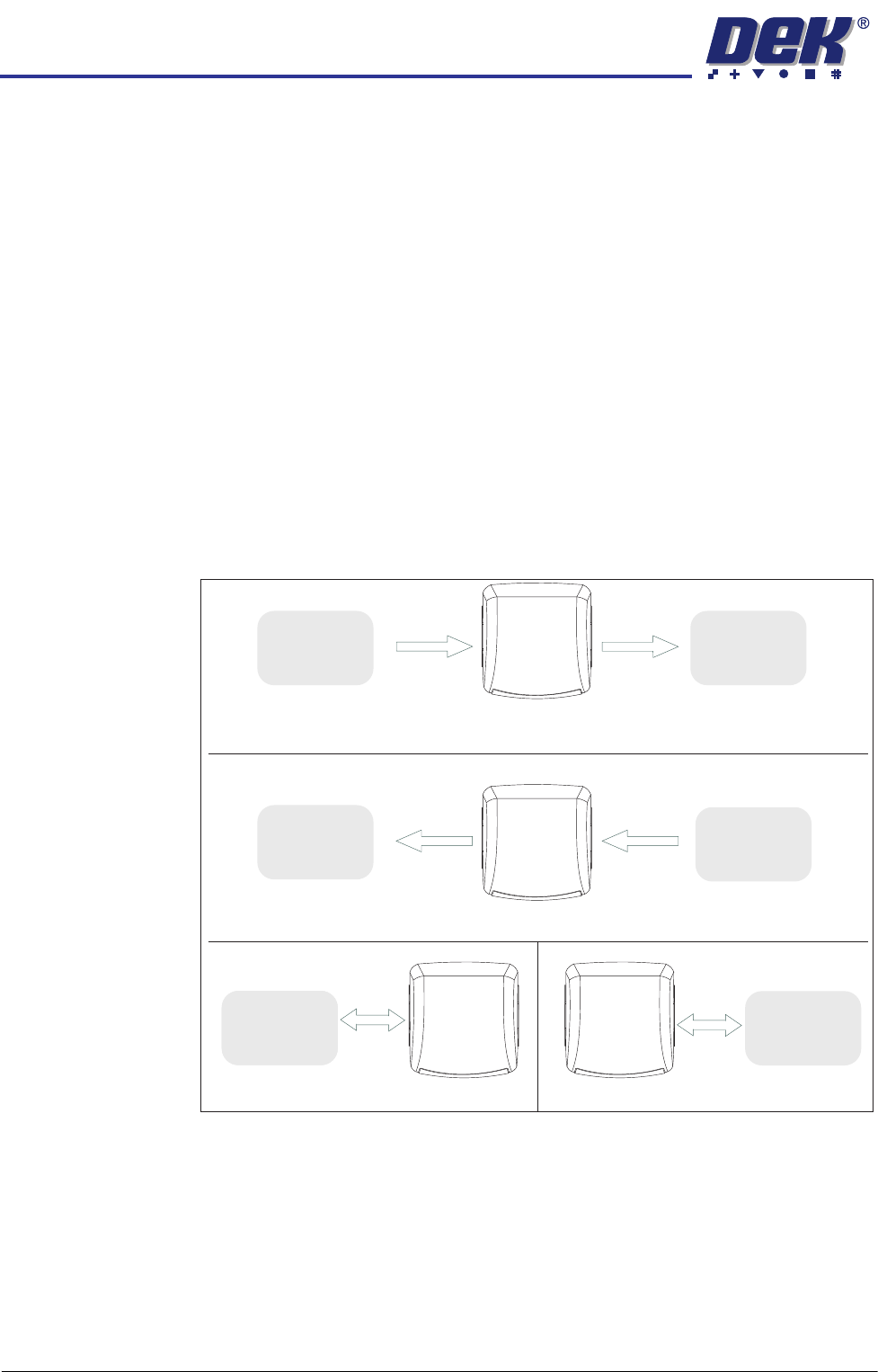
Figure 3-4 Process Direction Options
Left to Right Pallet Transfers
Right to Left Pallet Transfers
Downline
Downline
Downline
Left to Left Pallet Transfers
Right to Right Pallet Transfers
DEK
Machine
DEK
Machine
DEK
Machine
DEK
Machine
Adjacent
Machine/
Conveyor
NOTE
Pallets can be manually fed into the printer
Adjacent
Machine/
Conveyor
Adjacent
Machine/
Conveyor
Upline
Adjacent
Machine/
Conveyor
Upline
Adjacent
Machine/
Conveyor
Upline
Adjacent
Machine/
Conveyor