00192791-02.pdf - 第40页
2 Ceramic S ubstrate Centering Unit User Manual S IPLACE HS-50 2.3 Mechanical Ceramic Substrate Centering Software Version SR.502.xx 01/01 Issue 40 Key: 4. Body 5. X-sli de unit 6. S top r ail 1, 2, or 3 (mo vable stop) …
User Manual 2 Ceramic Substrate Centering Unit
Software Version SR.502.xx 01/01 Issue 2.3 Mechanical Ceramic Substrate Centering
39
'HVFULSWLRQRI)XQFWLRQ
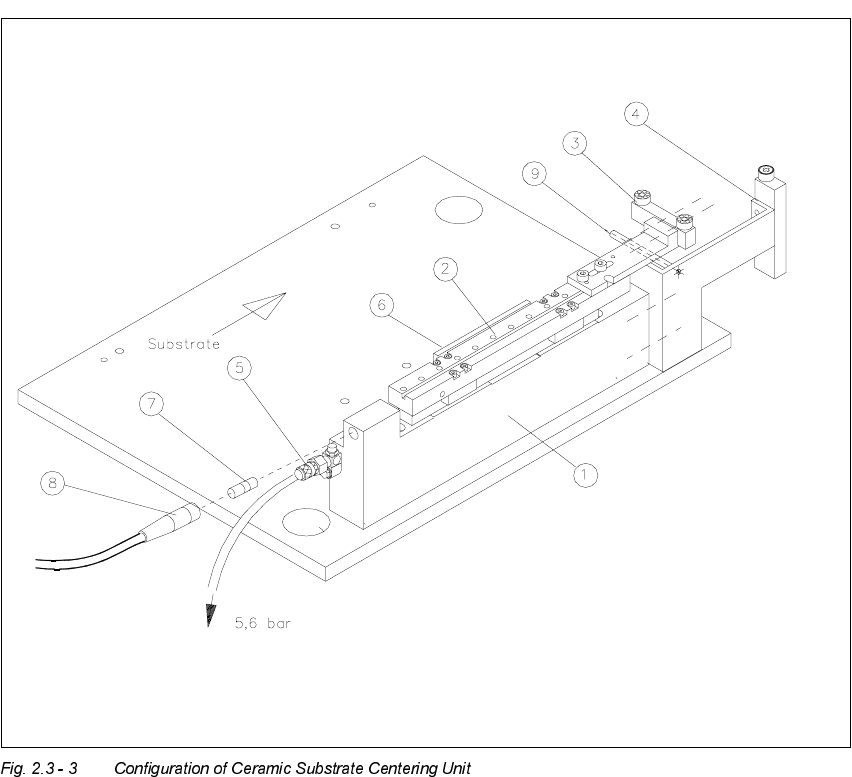
The major components of the mechanical ceramic substrate centering unit are the X-slide unit with
centering jaws which consists of a stop rail and stop unit at the front of the centering unit, a flat
cylinder with 5.6 bar compressed air connection, resetting spring, and inductive proximity switch
at the back (see Fig 2.3 - 3), that signals the condition "Centering unit open".
The triggering of the mechanical ceramic substrate centering and the monitoring of the proximity
switch are activated by the conveyor control. If an error occurs, the message "Error ceramic sub-
strate centering 1 / 2" is output at the station’s operating interface (see Section 2.3.6).
During the placement run, the substrate - like a PCB - is transported into the processing area
1 / 2 or 4 / 3 where it is recorded by the ultrasonic sensor. The stopper thereupon moves out, prep-
ositioning the substrate in X-direction, and the stopper then moves back.
When the ceramic substrate centering unit is open (in which state compressed air is present at
the ceramic substrate centering unit), it is lifted into the area of the substrate by the lifting table
and the signal "Lifting table at top" is triggered.
The mechanical X-centering follows: The pressure in the centering unit drops to zero. As a con-
sequence, the X-slide unit of the ceramic substrate centering unit moves forward and centers the
substrate in the X-direction (= transport direction) with the help of a tension spring between the
two ball bearings of the stop rail and the roller on the stop unit.
Following position recognition and completion of placement, the pressure of the compressed air
is exerted, opening the mechanical substrate centering unit.
The inductive proximity switch on the centering unit is tripped (switch signal => 1). When this sig-
nal "Ceramic substrate centering unit open" is received, the lifting table moves down with the open
centering unit and thus moves out of the path where substrates are transported.
The substrate is transported into the next conveyor area (intermediate conveyor / output con-
veyor).
2 Ceramic Substrate Centering Unit User Manual SIPLACE HS-50
2.3 Mechanical Ceramic Substrate Centering Software Version SR.502.xx 01/01 Issue
40
Key:
4. Body
5. X-slide unit
6. Stop rail 1, 2, or 3 (movable stop) with 2 ball bearings for 50 mm to 140 mm,
fastened with 2 socket head cap screws M3 x 8
7. Stop unit kit 1, 2 or 3 (fixed stop) with stationary roller of plastic AND distance bolt:
for 50 mm to 140 mm
8. Compressed air connection 5.6 bar / pneumatic hose
9. Flat cylinder and tension spring
10.Proximity switch
11.Proximity switch cable with plug-in connection
12.Distance bolt
User Manual 2 Ceramic Substrate Centering Unit
Software Version SR.502.xx 01/01 Issue 2.3 Mechanical Ceramic Substrate Centering
41
$GDSWLQJWRWKH6XEV WUDWH6 L]H
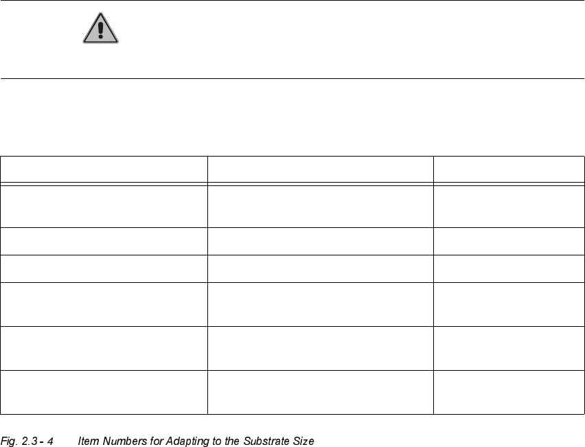
The ceramic substrate centering unit is adapted to the substrate size that is to be processed next
by installing the appropriate stop rail and the appropriate stop unit (Item no.: see table,
Fig. 2.3 - 4, below).
CAUTION
The distance bolt on the stop unit (kit 1, 2 or 3) WITH distance bolt is not to remove !
The following components (see also Fig. 2.3 - 5) are required for the adapting:
Designation For substrate width Item no.
Stop rail 1 assembly
with parallel pin
for 50 mm to 62 mm 00358877-01
Stop rail 2 assembly for > 62 mm to 106 mm 00358884-01
Stop rail 3 assembly for > 106 mm to 140 mm 00358885-01
Stop unit kit 1 (complete
with distance bolt)
for 50 mm to 62 mm 00358874-01
Stop unit kit 2 (complete
with distance bolt)
for > 62 mm to 106 mm 00358875-01
Stop unit kit 3 (complete
with distance bolt)
for > 106 mm to 140 mm 00358876-01