00192791-02.pdf - 第42页
2 Ceramic S ubstrate Centering Unit User Manual S IPLACE HS-50 2.3 Mechanical Ceramic Substrate Centering Software Version SR.502.xx 01/01 Issue 42 Key: 1. S top un it Ki t 1, fixed stop 2. S top un it Ki t 2, fixed stop…
User Manual 2 Ceramic Substrate Centering Unit
Software Version SR.502.xx 01/01 Issue 2.3 Mechanical Ceramic Substrate Centering
41
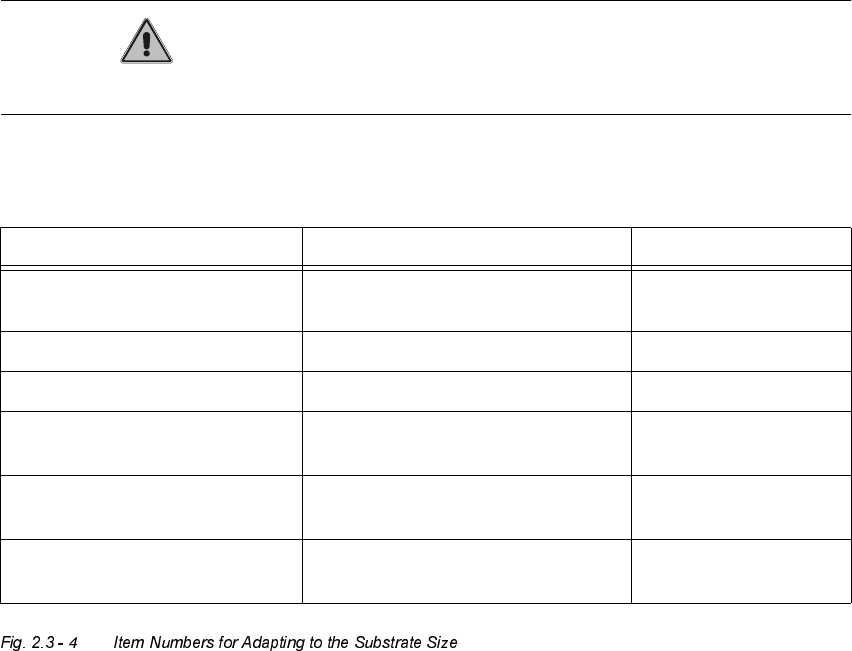
$GDSWLQJWRWKH6XEV WUDWH6 L]H
The ceramic substrate centering unit is adapted to the substrate size that is to be processed next
by installing the appropriate stop rail and the appropriate stop unit (Item no.: see table,
Fig. 2.3 - 4, below).
CAUTION
The distance bolt on the stop unit (kit 1, 2 or 3) WITH distance bolt is not to remove !
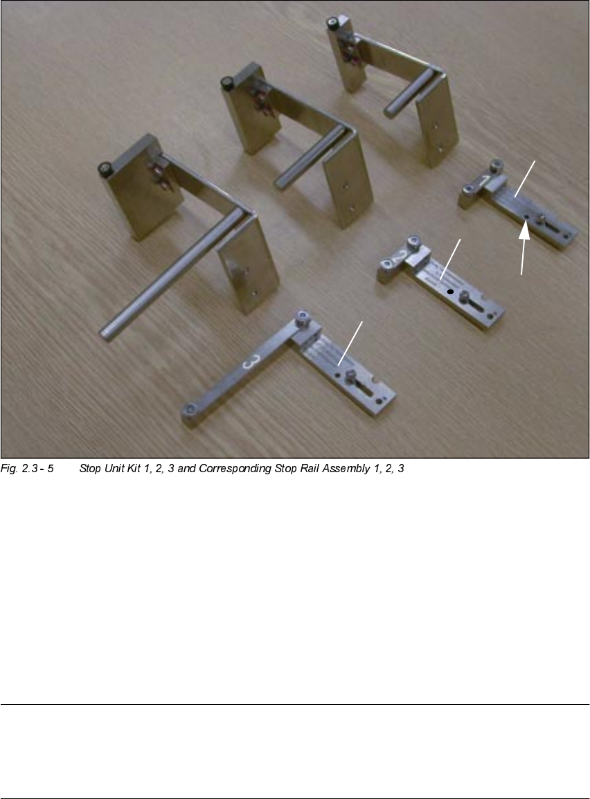
The following components (see also Fig. 2.3 - 5) are required for the adapting:
Designation For substrate width Item no.
Stop rail 1 assembly
with parallel pin
for 50 mm to 62 mm 00358877-01
Stop rail 2 assembly for > 62 mm to 106 mm 00358884-01
Stop rail 3 assembly for > 106 mm to 140 mm 00358885-01
Stop unit kit 1 (complete
with distance bolt)
for 50 mm to 62 mm 00358874-01
Stop unit kit 2 (complete
with distance bolt)
for > 62 mm to 106 mm 00358875-01
Stop unit kit 3 (complete
with distance bolt)
for > 106 mm to 140 mm 00358876-01
2 Ceramic Substrate Centering Unit User Manual SIPLACE HS-50
2.3 Mechanical Ceramic Substrate Centering Software Version SR.502.xx 01/01 Issue
42
Key:
1. Stop unit Kit 1, fixed stop
2. Stop unit Kit 2, fixed stop
3. Stop unit Kit 2, fixed stop
4. Stop rail 1, 2 and 3, assembly (see marks
and
), movable stop
5. Parallel pin to limit the lift:
MUST be on stop rail 1.
NOTE:
Install the stop unit kit 1 (fixed stop) and stop rail "", assembly (= movable stop) for substrates
50mm to 62mm wide that are MORE than 50mm long (e. g., twice as long): See table,
Fig. 2.3 - 4, above and Fig. 2.3 - 5).

User Manual 2 Ceramic Substrate Centering Unit
Software Version SR.502.xx 01/01 Issue 2.3 Mechanical Ceramic Substrate Centering
43
DANGER
Only the line engineer is permitted to perform the following work.
The safety instructions in the chapter "Operational Safety" in the User Manual HS-50 take prece-
dence.
BEFORE any work, the machine must be switched OFF and isolated from the mains.
In addition, the compressed air feed must be switched OFF at the main valve of the compressed
air unit in the machine frame.
While working, secure the machine conscientiously against other persons and against being re-
started without authority. Proceed as described in the chapter "Locking of the Machine".
Å The movable component changeover table remains moved into place and connected.
Å Turn the machine OFF as described in the above DANGER text.
Å The mechanical ceramic substrate centering unit is left installed during the adapting to the sub-
strate size.
Å Move the Y-gantry in such a manner that the ceramic substrate centering unit is readily acces-
sible.
Å Loosen the screws fastening the stop rail to the X-slide unit (2 socket head hex cap screws M3:
see Fig. 2.3 - 6).
Å Install the stop rail required based on the substrate size (see table above).