00192791-02.pdf - 第48页
2 Ceramic S ubstrate Centering Unit User Manual S IPLACE HS-50 2.3 Mechanical Ceramic Substrate Centering Software Version SR.502.xx 01/01 Issue 48 Key to 2.3 - 7, continued: 1. S to pper axl es (on dual conv eyor: co nt…

User Manual 2 Ceramic Substrate Centering Unit
Software Version SR.502.xx 01/01 Issue 2.3 Mechanical Ceramic Substrate Centering
47
$GMXVWLQJWKH6WRSSHU3RVLWLRQ
DANGER
Only the line engineer is permitted to perform the following work.
The safety instructions in the chapter "Operational Safety" in the User Manual HS-50 take prece-
dence.
BEFORE any work, the machine must be switched OFF and isolated from the mains.
In addition, the compressed air feed must be switched OFF at the main valve of the compressed
air unit in the machine frame.
While working, secure the machine conscientiously against other persons and against being re-
started without authority. Proceed as described in the chapter "Locking of the Machine".
.H\
A) PCB / substrate transport direction
B) Direction for adjusting the postion of the stopper
2 Ceramic Substrate Centering Unit User Manual SIPLACE HS-50
2.3 Mechanical Ceramic Substrate Centering Software Version SR.502.xx 01/01 Issue
48
Key to 2.3 - 7, continued:
1. Stopper axles (on dual conveyor: continuous axles for belt 2)
2. Stopper assembly
3. Connection rail on fixed and movable side of the conveyor
4. Fastening for the connection rails: 2 socket hex head cap screws M4
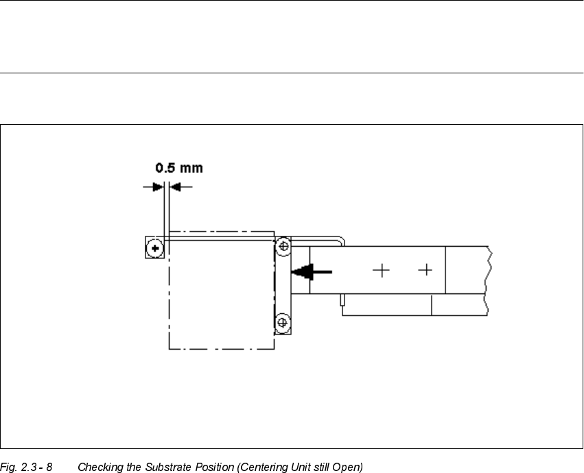
NOTE:
As shown below, the substrate edge pointing toward the unloader must still be 0.5 mm IN FRONT
OF that of the unmovable roller of the fixed stop while the centering unit is open.
Å In processing area 1 loosen the screws fastening the connection rail on inside left and inside
right of the conveyor assemblies (2 socket hex head cap screws M 4 each).
Å Move the connection rails (incl. guide axles and stopper) the required diistance in PARALLEL
in the direction of the ceramic substrate centering unit and retighten the screws to fasten the
connection rails in this position.
Å Conduct a trial placement with substrate and check whether the substrate can be centered.
User Manual 2 Ceramic Substrate Centering Unit
Software Version SR.502.xx 01/01 Issue 2.3 Mechanical Ceramic Substrate Centering
49
&KDQJHIURP&HUDPLF6 XEVWUDW H&H QWHULQJWR3&%&OD PSLQJ
Only the service engineer is permitted to do the reinstallation and must do so on the basis of the
Service Manual or the Retrofitting Manual.
For this purpose the mechanical ceramic substrate centering units of the two processing areas of
the pertinent conveyor must be isolated electrically and pneumatically and then disassembled.
The connection rails from the retrofit kit must be installed on the pertinent conveyor assemblies.