00192791-02.pdf - 第50页
2 Ceramic S ubstrate Centering Unit User Manual S IPLACE HS-50 2.4 Weekly Maintenance Software Version SR.502.xx 01/01 Issue 50 : HHNO\ 0DLQWHQDQFH DANGER In additio n to the se instruc tions, y ou will always n eed…
User Manual 2 Ceramic Substrate Centering Unit
Software Version SR.502.xx 01/01 Issue 2.3 Mechanical Ceramic Substrate Centering
49
&KDQJHIURP&HUDPLF6 XEVWUDW H&H QWHULQJWR3&%&OD PSLQJ
Only the service engineer is permitted to do the reinstallation and must do so on the basis of the
Service Manual or the Retrofitting Manual.
For this purpose the mechanical ceramic substrate centering units of the two processing areas of
the pertinent conveyor must be isolated electrically and pneumatically and then disassembled.
The connection rails from the retrofit kit must be installed on the pertinent conveyor assemblies.
2 Ceramic Substrate Centering Unit User Manual SIPLACE HS-50
2.4 Weekly Maintenance Software Version SR.502.xx 01/01 Issue
50
:HHNO\0DLQWHQDQFH
DANGER
In addition to these instructions, you will always need the current edition of the "Maintenance Man-
ual for HS-50", Item no. 00191375-02, to restore the machine to its original safe condition in terms
of maintenance and to perform all of other the jobs specified for this maintenance period.
During all maintenance work, comply with the safety instructions in Chapter 1 of the above-men-
tioned "Maintenance Manual for HS-50". It also contains the explanation for the symbols used.
Perform the maintenance work described while conducting the "Vacuuming Off the PCB Con-
veyor" described below during the weekly maintenance work on the "Mechanical Ceramic Center-
ing Unit".
The maintenance must be performed on ALL of existing centering units (see Fig. 2.3 - 1).
7UDQVSRUWGLUHFWLRQ
0[
6WRSXQLW

User Manual 2 Ceramic Substrate Centering Unit
Software Version SR.502.xx 01/01 Issue 2.4 Weekly Maintenance
51
7RROV$X[L OLDU\7HVW( TXLSPHQWDQG( [SHQGDEOH 0DWHU LDOV
– Vacuum cleaner (with suitable nozzle)
– Tweezers
– If applicable, Cross-slotted screwdriver, size 1
– If applicable, Seeger pliers for shaft circlip ring
– If applicable, roller for fixed stop, Item no. Art.-Nr. 00347284-01
– If applicable, screw to fasten the roller, M3 x 8 DIN 965 (Item no. 00095305-01)
– If applicable, tension spring for flat cylinder, Item no. 00359769-01
– If applicable, circlip for spring suspension pin, Item no. 00048315-01
3UHSDUDWRU\ 6WHSV
Å Establish the maintenance condition of the machine and the accessibility of the work area.
Proceed as described for the cleaning of the PCB conveyor in the section "Weekly Mainte-
nance", in the "Maintenance Manual for HS-50".
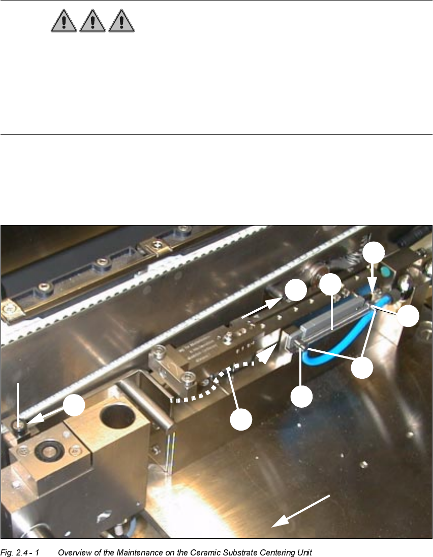
&OHDQLQJWKH6OL GH*XLGH
Components located in the positioning range of the slide guide of the ceramic substrate centering
unit may result in incorrect centering or to an error message and stoppage of the placement pro-
cess -> Proximity switch signal for "Centering unit open" is not actuated.
Å Thoroughly vacuum off the slide guide in the front area (see Fig. 2.4 - 1 -> Pos. 3) and in the
area of the end stop, at back (see Pos. 1).
Å Remove the jammed component with tweezers.
Å Push the slide of the centering unit (see Pos. 2) all the way against the back stop and thor-
oughly vacuum off the portion of the slide guide that is now exposed at the front.
Å The make certain that the slide moves smoothly.
Å It must be possible to open the centering unit entirely (as far as the stop on the back) and to
close it entirely.
If you note a problem with the tension spring during this process, resume with the work in Sec-
tion 1.